

UML Class Diagram Tutorial
Why use a uml diagram.
Class diagrams are one of the most useful types of diagrams in UML as they clearly map out the structure of a particular system by modeling its classes, attributes, operations, and relationships between objects. With our UML diagramming software, creating these diagrams is not as overwhelming as it might appear. This guide will show you how to understand, plan, and create your own class diagrams.
8 minute read
Do you want to create your own UML diagram? Try Lucidchart. It's fast, easy, and totally free.
What is a class diagram in UML?
UML was set up as a standardized model to describe an object-oriented programming approach. Since classes are the building block of objects, class diagrams are the building blocks of UML. The various components in a class diagram can represent the classes that will actually be programmed, the main objects, or the interactions between classes and objects.
The class shape itself consists of a rectangle with three rows. The top row contains the name of the class, the middle row contains the attributes of the class, and the bottom section expresses the methods or operations that the class may use. Classes and subclasses are grouped together to show the static relationship between each object.
The UML shape library in Lucidchart can help you create nearly any custom class diagram using our UML diagram tool.

Benefits of class diagrams
Class diagrams offer a number of benefits for any organization. Use UML class diagrams to:
- Illustrate data models for information systems, no matter how simple or complex.
- Better understand the general overview of the schematics of an application.
- Visually express any specific needs of a system and disseminate that information throughout the business.
- Create detailed charts that highlight any specific code needed to be programmed and implemented to the described structure.
- Provide an implementation-independent description of types used in a system that are later passed between its components.
Basic components of a class diagram
The standard class diagram is composed of three sections:
Upper section:
Middle section:, bottom section:, member access modifiers.
All classes have different access levels depending on the access modifier (visibility). Here are the access levels with their corresponding symbols:
- Private (-)
- Protected (#)
- Package (~)
- Derived (/)
- Static (underlined)
Member scopes
There are two scopes for members: classifiers and instances.
Classifiers are static members while instances are the specific instances of the class. If you are familiar with basic OO theory, this isn't anything groundbreaking.
Additional class diagram components
Depending on the context, classes in a class diagram can represent the main objects, interactions in the application, or classes to be programmed. To answer the question "What is a class diagram in UML?" you should first understand its basic makeup.
Attributes:
Data types:, interfaces: , enumerations:, interactions.
The term "interactions" refers to the various relationships and links that can exist in class and object diagrams. Some of the most common interactions include:
Inheritance:

In this example, the object "Car" would inherit all of the attributes (speed, numbers of passengers, fuel) and methods (go(), stop(), changeDirection()) of the parent class ("Vehicle") in addition to the specific attributes (model type, number of doors, auto maker) and methods of its own class (Radio(), windshieldWiper(), ac/heat()). Inheritance is shown in a class diagram by using a solid line with a closed, hollow arrow.
Bidirectional association:

In the example above, the Car class and RoadTrip class are interrelated. At one end of the line, the Car takes on the association of "assignedCar" with the multiplicity value of 0..1, so when the instance of RoadTrip exists, it can either have one instance of Car associated with it or no Cars associated with it. In this case, a separate Caravan class with a multiplicity value of 0..* is needed to demonstrate that a RoadTrip could have multiple instances of Cars associated with it. Since one Car instance could have multiple "getRoadTrip" associations—in other words, one car could go on multiple road trips—the multiplicity value is set to 0..*
Unidirectional association:

As an example, on your road trip through Arizona, you might run across a speed trap where a speed cam records your driving activity, but you won't know about it until you get a notification in the mail. It isn't drawn in the image, but in this case, the multiplicity value would be 0..* depending on how many times you drive by the speed cam.
Class diagram examples
Creating a class diagram to map out process flows is easy. Consider the two examples below as you build your own class diagrams in UML.
Class diagram for a hotel management system
A class diagram can show the relationships between each object in a hotel management system, including guest information, staff responsibilities, and room occupancy. The example below provides a useful overview of the hotel management system. Get started on a class diagram by clicking the template below.

Class diagram for an ATM system
ATMs are deceptively simple: although customers only need to press a few buttons to receive cash, there are many layers of security that a safe and effective ATM must pass through to prevent fraud and provide value for banking customers. The various human and inanimate parts of an ATM system are illustrated by this easy-to-read diagram—every class has its title, and the attributes are listed beneath. You can edit, save, and share this chart by opening the document and signing up for a free Lucidchart account.

Click here to use this template
How to make a class diagram
In Lucidchart, creating a class diagram from scratch is surprisingly simple. Just follow these steps:
Open a blank document or start with a template.
Enable the UML shape library. On the left side of the Lucidchart editor, click "Shapes." Once you're in the Shape Library Manager, check "UML" and click "Save."
From the libraries you just added, select the shape you want and drag it from the toolbox to the canvas.
Model the process flow by drawing lines between shapes while adding text.
Dive into this guide on how to draw a class diagram in UML for additional insight. In Lucidchart, it's easy to resize and style any element. You can even import SVG shapes and Visio files for a custom solution. If you'd like to learn more about UML, check out our tutorial, " What Is UML ?"
Additional Resources
- Communication Diagram Tutorial
- How to Draw a Sequence Diagram in UML
- All about composite structure diagrams
- System Sequence Diagrams in UML
- UML Sequence Diagram Tutorial
- State Machine Diagram Tutorial
- All about UML interaction diagrams
- All about UML package diagrams
- How to Draw an Object Diagram in UML
- How to Draw a Timing Diagram in UML
- How to Draw a Deployment Diagram in UML
- How to Draw a State Machine Diagram in UML
- How to Draw a Communication Diagram in UML
- How to Draw a Component Diagram in UML
- How to Draw a Class Diagram in UML
- Deployment Diagram Tutorial
- Timing Diagram Tutorial
- UML Use Case Diagram Tutorial
- Object Diagram Tutorial
- UML Activity Diagram Tutorial
- What is Unified Modeling Language
- Component Diagram Tutorial
Class diagrams are one of the most common types of diagrams in UML, and Lucidchart has made it easy to understand and create them. Jump right into one of our templates, import an existing class diagram and continue working on it within Lucidchart, or start from scratch. We have all the features and tools you need to get started.
We use essential cookies to make Venngage work. By clicking “Accept All Cookies”, you agree to the storing of cookies on your device to enhance site navigation, analyze site usage, and assist in our marketing efforts.
Manage Cookies
Cookies and similar technologies collect certain information about how you’re using our website. Some of them are essential, and without them you wouldn’t be able to use Venngage. But others are optional, and you get to choose whether we use them or not.
Strictly Necessary Cookies
These cookies are always on, as they’re essential for making Venngage work, and making it safe. Without these cookies, services you’ve asked for can’t be provided.
Show cookie providers
- Google Login
Functionality Cookies
These cookies help us provide enhanced functionality and personalisation, and remember your settings. They may be set by us or by third party providers.
Performance Cookies
These cookies help us analyze how many people are using Venngage, where they come from and how they're using it. If you opt out of these cookies, we can’t get feedback to make Venngage better for you and all our users.
- Google Analytics
Targeting Cookies
These cookies are set by our advertising partners to track your activity and show you relevant Venngage ads on other sites as you browse the internet.
- Google Tag Manager
- Infographics
- Daily Infographics
- Graphic Design
- Graphs and Charts
- Data Visualization
- Human Resources
- Training and Development
- Beginner Guides
Blog Graphs and Charts
How to Make a Class Diagram [+Examples]
By Letícia Fonseca , Jun 08, 2023

Class diagrams are static structures used to show class relationships in object-oriented programming.
They are a good way to show the class structure of a system. For organizations, class diagrams help illustrate class relationships in a business application.
A class diagram is especially useful for communicating class hierarchies and class collaborations with stakeholders or a team.
Interested in creating a class diagram but not sure how? Check out our uml diagram maker , which makes it easy to make your own object diagrams.
Or why not browse our customizable diagram templates where the hard is already done for you?
Read on to learn more about how you can make your own class diagram.
Click to jump ahead:
What is a class diagram, what are the benefits of using a class diagram.
- Class diagram examples
Understanding class diagrams: Symbols and notations
- Best practices in designing class diagrams
- How to make a class diagram
FAQs about class diagrams
A class diagram is a visual representation of class objects in a model system, categorized by class types . Each class type is represented as a rectangle with three compartments for the class name, attributes, and operations.
To understand a class diagram, we must first define what a class is.
A class represents the main program unit in object-oriented programming. Classes are data structures that contain code and represent objects in an application.

Objects are represented as ovals that contain class names inside class name compartments. Attributes are listed inside the attribute compartment, while class operations are listed below the class rectangle.
What is the difference between class diagrams and UML diagrams?
Class diagrams are a type of UML (unified modeling language) diagram which are used to describe model systems.
The main difference between a class diagram and a UML diagram is that a class diagram shows class structure while other types of UML class diagrams follow different conventions.
Instead of class operations, some UML diagrams include messages sent between objects.
In a class diagram, relationships (associations) between classes are shown as lines with an arrow at one or both ends which indicate class ownership or dependency.
Using a class diagram is a good way for businesses to communicate a class structure to project stakeholders and teams.
A class diagram is especially useful for communicating class hierarchies and collaborations between classes.
What are class diagrams used for?
Class diagrams have several use cases.
Here are a few examples of how they help developers and businesses:
- Visualize class relationships
- Design class structure
- Plan software development
- Support code generation
A popular utility of class diagrams is their ability to showcase the class structure of a system. They help illustrate how classes interact with each other and enable developers to grasp the overall architecture of a system.
Moreover, class diagrams facilitate the design process by allowing developers to define and communicate attributes and methods, leading to an organized codebase.
Class diagrams are also popular in the early development stages of a project as they can be used to communicate with stakeholders, leading to informed decisions.
Last but not least, class diagrams can also be used for requirements analysis by communicating what business processes are included in the application.
Examples of class diagrams for businesses
In businesses, class diagrams provide a way to describe a business system and its components.
They also exhibit how a model system is divided into parts and the relationships between those parts.
Class diagrams are used throughout process modeling which can be done with Unified Modeling Language (UML) software.
Here are some examples of how class diagrams are used for business systems:
ATM Usage

This is an example of how a class diagram is used to present the backend system of an ATM Machine.
The ATM model system has a card reader, a bank account holder, and a printer. Each component can send information to the other as well as to the machine itself while maintaining layers of security to keep your bank account protected.
Passenger Services IT System

This class diagram is an example of a passenger services IT system.
The diagram presents how data from a passenger can be converted into a complete set of information complete with flight details and the aircraft that will be used.
Hospital Management System

This class diagram presents a hospital management system.
It showcases all people involved in the business process of hospital management, presenting the different relationships between healthcare workers and patients.
It also provides an overview of how a hospital works through its operational, administrative, and technical functions.
Class diagrams use symbols and notations to help illustrate class structures.
Here are some common notations and symbols to help you better understand class diagrams:
Class diagram notations
Classes are represented by rectangles with three compartments for class names, attributes, and operations.
A rectangle with double borders represents an abstract class that cannot be instantiated. Each subclass is depicted by a rectangle inside each superclass’ compartment, with the same notation as the superclass’.
Objects are represented as ovals that contain class names inside class name compartments.
A single object is depicted by an oval that contains only one class name inside the object’s class compartment. If there are multiple classes, then the ovals are nested inside each other to represent which objects contain which classes.
Attributes are listed inside the attribute compartment of a class rectangle. Attributes can be either attributes or operations of a class depending on whether they are used in an association relationship with another class.
Class diagram symbols

Objects (including classes, object occurrences, and attributes) usually have an arrowed association line to indicate the type of relationship.
The line will either join two objects together or represent a single object’s attribute if it is defined in another class.
When there is more than one association between two classes, a connector is used to show these relationships by drawing lines between objects representing the classes.

A single object can be represented by a circle inside a subclass compartment if there is only one instance of the class.
If multiple objects are created from one class, then each class object is represented by a box inside the superclass compartment and an oval shape inside each box for each of the objects.

A diamond can be used to represent a class that contains many subclasses or many classes depending on the position of the diamond.
The open end indicates that it has subclasses while the closed end represents multiple classes.

A rectangle with one compartment is an abstract class that cannot be instantiated, while rectangles with two compartments represent concrete classes that can be instantiated.
A class may use a rectangle with three compartments to indicate attributes and operations, or it can simply use the traditional rectangle notation described above.
5 best practices for making class diagrams
Here are 5 best practices for making class diagrams:
Practice 1 – Make sure your class diagrams are simple and easy to understand
Class diagram design should be kept as simple as possible.
Don’t create unnecessary complexity by using more than two levels of hierarchy or too many abstract classes.
Your goal is to help the audience understand what your class model consists of at a glance, so you need to keep the design straightforward.
Practice 2- Keep all associations and relationships short
Class diagrams should be easy to read with no unnecessary elements as that will only make it harder for the audience to focus on what is important.
Shorten any relationships as much as you can without losing the purpose of the association.
Practice 3 – Only include necessary attributes and operations
Keep in mind that class diagrams are supposed to make things simple, not complicated.
You don’t need to show all attributes or operations of every class. Only include those that will help describe how a class relates to other classes or on its own.
Practice 4 – Use standard symbols when possible
There are standardized symbols you can use for class diagrams in case there are no available templates.
Stick to the standards whenever you can unless your diagrams will make more sense using other symbols. Use different shapes to represent classes, objects, attributes, and operations if needed.
Practice 5 – Don’t forget about multiple inheritances
If you decide to use multiple inheritances then keep in mind that one class can inherit from more than one other class.
You will need to show all of the inherited classes inside the same compartment, and indicate the order in which they were inherited if they’re not on top of each other.
How to make a class diagram ?
There are several ways you can make a class diagram.
Let’s explore a few different methods:
Manually create your own with Microsoft PowerPoint

Microsoft PowerPoint allows you to manually create your diagram and test ideas quickly.
While this can be useful in coming up with your class diagrams, using PowerPoint can take up a lot of time and will not support all of the features in UML.
Generate a class diagram based on a code with Microsoft Visio

An application like Microsoft Visio can be used to create class diagrams by automatically generating UML class elements based on the code in your programming language.
This can be a great way to automatically generate documentation for each class in your system.
While Visio is an excellent tool for creating diagrams, it can be quite daunting especially when you’re new to class diagrams.
Use a class diagram template and customize it with Venngage

Venngage’s diagram maker allows you to create class diagrams without any coding by simply dragging and dropping shapes onto the page.
You can add your own shapes or text to make them more specific to your system.
Editing the templates in Venngage is easy and allows you to try different styles, making it a great tool for diagrams, whether you’re a beginner or an expert at class diagrams.
Venngage also has a business feature called My Brand Kit that enables you to add your company’s logo, color palette, and fonts to all your designs with a single click.
For example, you can make your template reflect your brand design by uploading your brand logo, fonts, and color palette using Venngage’s branding feature.
Not only are Venngage templates free to use and professionally designed, but they are also tailored for various use cases and industries to fit your exact needs and requirements.
A business account also includes the real-time collaboration feature , so you can invite members of your team to work simultaneously on a project.
Venngage allows you to share your class diagram design online as well as download it as a PNG or PDF file. That way, your design will always be presentation-ready.
What does a class diagram include?
The primary components of a class diagram are classes, objects, attributes, operations, associations, generalizations, and stereotypes.
What is a class diagram method?
A class diagram method is an approach to creating class diagrams. There are different approaches that you can use, including the top-down, bottom-up, and code first methods. These methods all have their advantages and disadvantages. For example, some may be better suited for object-oriented design while others might be more useful when designing an application with a team of developers.
How do you write a class diagram?
You can write a class diagram by creating one in Microsoft PowerPoint or Word, using an application like Microsoft Visio, or using an online tool like Venngage. While there are advantages and disadvantages to each program, using an online tool like Venngage is a good way to create a class diagram quickly and easily.
Build stronger business processes with class diagrams
Class diagrams are great for making complex systems easier to understand.
Whether you’re using them for business processes or creating an object-oriented design, class diagrams are useful tools for working with large amounts of information.
If you want to create your own diagrams, there is a wide range of applications that you can use to create your own.
However, if you want to get the job done quickly without needing to code, you can use Venngage to help you find the best chart to illustrate your ideas visually.
All you have to do is choose a template from a wide range of class and object diagrams that you can customize with the drag-and-drop editor. Sign up for a free account on Venngage and create your class diagrams with ease.

The Easy Guide to UML Class Diagrams | Class Diagram Tutorial
Updated on: 5 January 2023
At the heart of any object-oriented system is the step of designing the class structure – therefore the saying goes that class diagrams are the most popular out of the UML diagram types.
In this easy class diagram tutorial, we’ve covered the key areas you need to know to draw class diagrams without a struggle. Scroll down to find out
- Class Diagram Definition
Class Diagram Notations with Examples
How to draw a class diagram, class diagram best practices.
- Class Diagram Examples/Templates
Class Diagram Definition | What is a Class Diagram?
A class diagram is a UML diagram type that describes a system by visualizing the different types of objects within a system and the kinds of static relationships that exist among them. It also illustrates the operations and attributes of the classes.
They are usually used to explore domain concepts, understand software requirements and describe detailed designs.
There are several class diagram notations that are used when drawing UML class diagrams . We’ve listed below the most common class diagram notations.

The first one shows the class’s name, while the middle one shows the class’s attributes which are the characteristics of the objects. The bottom one lists the class’s operations, which represents the behavior of the class.

Simple Class
The last two compartments are optional. The class notation without the last two compartments is called a simple class and it only contains the name of the class.

Class Diagram Relationships

To learn about the class diagram connector types and the different relationships between classes in detail, refer to our handy guide on class diagram relationships .
For a full list of class diagram notations/ class diagram symbols refer to this post .
Class diagrams go hand in hand with object-oriented design . So knowing its basics is a key part of being able to draw good class diagrams.
When required to describe the static view of a system or its functionalities, you’d be required to draw a class diagram . Here are the steps you need to follow to create a class diagram.
Step 1: Identify the class names
The first step is to identify the primary objects of the system.
Step 2: Distinguish relationships
Next step is to determine how each of the classes or objects are related to one another. Look out for commonalities and abstractions among them; this will help you when grouping them when drawing the class diagram.
Step 3: Create the Structure
First, add the class names and link them with the appropriate connectors. You can add attributes and functions/ methods/ operations later.
- Class diagrams may tend to get incoherent as they expand and grow. It’s best to avoid creating large diagrams and breaking them down into smaller ones that you can link to each other later. You can very easily do this with Creately. It helps you improve the readability of your diagrams.
- Using the simple class notation, you can quickly create a high-level overview of your system. A detailed diagram can be created separately as required, and even linked to the first one for easy reference.
- The more lines overlap on your class diagrams, the more cluttered it becomes. The reader will only get confused trying to find the path. Make sure that no two lines cross each other.
- Use colors to group common modules. Different colors on different classes help the reader differentiate between the various groups.
Class Diagram Examples / Templates
Class diagram example 1.
Click on the template to edit it online
Class Diagram Example 2

Class Diagram Example 3

Other Class Diagram Resources
- Guidelines for UML Class Diagrams – Part 1
- Guidelines for UML Class Diagrams – Part 2
- Tools, Templates and Resources to Draw Class Diagrams
Share Your Thoughts on the Class Diagram Tutorial
In this class diagram tutorial, we’ve covered what a class diagram is, class diagram notations, how to draw a class diagram and best practices you can follow when creating class diagrams. In addition, we’ve added a few class diagram examples that you can instantly edit online.
Interested in learning about other UML diagram types ?
Join over thousands of organizations that use Creately to brainstorm, plan, analyze, and execute their projects successfully.

More Related Articles
Leave a comment Cancel reply
Please enter an answer in digits: 15 − 6 =
Download our all-new eBook for tips on 50 powerful Business Diagrams for Strategic Planning.
- Demo Videos
- Interactive Product Tours
- Request Demo
UML Class Diagram Tutorial
The UML Class diagram is a graphical notation used to construct and visualize object oriented systems. A class diagram in the Unified Modeling Language (UML) is a type of static structure diagram that describes the structure of a system by showing the system's:
- their attributes,
- operations (or methods),
- and the relationships among objects.
Learn UML Faster, Better and Easier
Are you looking for a Free UML tool for learning UML faster, easier and quicker? Visual Paradigm Community Edition is a UML software that supports all UML diagram types. It is an international award-winning UML modeler, and yet it is easy-to-use, intuitive & completely free.
What is a Class?
A Class is a blueprint for an object. Objects and classes go hand in hand. We can't talk about one without talking about the other. And the entire point of Object-Oriented Design is not about objects, it's about classes, because we use classes to create objects. So a class describes what an object will be, but it isn't the object itself.
In fact, classes describe the type of objects, while objects are usable instances of classes. Each Object was built from the same set of blueprints and therefore contains the same components (properties and methods). The standard meaning is that an object is an instance of a class and object - Objects have states and behaviors.
A dog has states - color, name, breed as well as behaviors -wagging, barking, eating. An object is an instance of a class.

UML Class Notation
A class represent a concept which encapsulates state ( attributes ) and behavior ( operations ). Each attribute has a type. Each operation has a signature . The class name is the only mandatory information .

Class Name:
- The name of the class appears in the first partition.
Class Attributes:
- Attributes are shown in the second partition.
- The attribute type is shown after the colon.
- Attributes map onto member variables (data members) in code.
Class Operations (Methods):
- Operations are shown in the third partition. They are services the class provides.
- The return type of a method is shown after the colon at the end of the method signature.
- The return type of method parameters are shown after the colon following the parameter name. Operations map onto class methods in code

Class Visibility
The +, - and # symbols before an attribute and operation name in a class denote the visibility of the attribute and operation.

- + denotes public attributes or operations
- - denotes private attributes or operations
- # denotes protected attributes or operations
Parameter Directionality
Each parameter in an operation (method) may be denoted as in, out or inout which specifies its direction with respect to the caller. This directionality is shown before the parameter name.

Perspectives of Class Diagram
The choice of perspective depends on how far along you are in the development process. During the formulation of a domain model , for example, you would seldom move past the conceptual perspective . Analysis models will typically feature a mix of conceptual and specification perspectives . Design model development will typically start with heavy emphasis on the specification perspective , and evolve into the implementation perspective .
A diagram can be interpreted from various perspectives:
- Conceptual : represents the concepts in the domain
- Specification : focus is on the interfaces of Abstract Data Type (ADTs) in the software
- Implementation : describes how classes will implement their interfaces
The perspective affects the amount of detail to be supplied and the kinds of relationships worth presenting. As we mentioned above, the class name is the only mandatory information.

Relationships between classes
UML is not just about pretty pictures. If used correctly, UML precisely conveys how code should be implemented from diagrams. If precisely interpreted, the implemented code will correctly reflect the intent of the designer. Can you describe what each of the relationships mean relative to your target programming language shown in the Figure below?
If you can't yet recognize them, no problem this section is meant to help you to understand UML class relationships. A class may be involved in one or more relationships with other classes. A relationship can be one of the following types:

Inheritance (or Generalization):
A generalization is a taxonomic relationship between a more general classifier and a more specific classifier. Each instance of the specific classifier is also an indirect instance of the general classifier. Thus, the specific classifier inherits the features of the more general classifier.
- Represents an "is-a" relationship.
- An abstract class name is shown in italics.
- SubClass1 and SubClass2 are specializations of SuperClass.
The figure below shows an example of inheritance hierarchy. SubClass1 and SubClass2 are derived from SuperClass. The relationship is displayed as a solid line with a hollow arrowhead that points from the child element to the parent element.

Inheritance Example - Shapes
The figure below shows an inheritance example with two styles. Although the connectors are drawn differently, they are semantically equivalent.

Association
Associations are relationships between classes in a UML Class Diagram. They are represented by a solid line between classes. Associations are typically named using a verb or verb phrase which reflects the real world problem domain.
Simple Association
- A structural link between two peer classes.
- There is an association between Class1 and Class2
The figure below shows an example of simple association. There is an association that connects the <<control>> class Class1 and <<boundary>> class Class2. The relationship is displayed as a solid line connecting the two classes.

Cardinality
Cardinality is expressed in terms of:
- one to many
- many to many

Aggregation
- A special type of association.
- It represents a "part of" relationship.
- Class2 is part of Class1.
- Many instances (denoted by the *) of Class2 can be associated with Class1.
- Objects of Class1 and Class2 have separate lifetimes.
The figure below shows an example of aggregation. The relationship is displayed as a solid line with a unfilled diamond at the association end, which is connected to the class that represents the aggregate.

Composition
- A special type of aggregation where parts are destroyed when the whole is destroyed.
- Objects of Class2 live and die with Class1.
- Class2 cannot stand by itself.
The figure below shows an example of composition. The relationship is displayed as a solid line with a filled diamond at the association end, which is connected to the class that represents the whole or composite.

An object of one class might use an object of another class in the code of a method. If the object is not stored in any field, then this is modeled as a dependency relationship.
- Exists between two classes if changes to the definition of one may cause changes to the other (but not the other way around).
- Class1 depends on Class2
The figure below shows an example of dependency. The relationship is displayed as a dashed line with an open arrow.

The figure below shows another example of dependency. The Person class might have a hasRead method with a Book parameter that returns true if the person has read the book (perhaps by checking some database).

Realization
Realization is a relationship between the blueprint class and the object containing its respective implementation level details. This object is said to realize the blueprint class. In other words, you can understand this as the relationship between the interface and the implementing class.
For example, the Owner interface might specify methods for acquiring property and disposing of property. The Person and Corporation classes need to implement these methods, possibly in very different ways.

Class Diagram Example: Order System

Class Diagram Example: GUI
A class diagram may also have notes attached to classes or relationships.

Try to Draw UML Class Diagram Now
You've learned what a Class Diagram is and how to draw a Class Diagram. It's time to draw a Class Diagram of your own. Get Visual Paradigm Community Edition, a free UML software, and create your own Class Diagram with the free Class Diagram tool. It's easy-to-use and intuitive.
Related Links
- What is Unified Modeling Language?
- Professional UML tool
Turn every software project into a successful one.
We use cookies to offer you a better experience. By visiting our website, you agree to the use of cookies as described in our Cookie Policy .
© 2024 by Visual Paradigm. All rights reserved.
- Privacy statement
UML Class Diagram Tutorial: Abstract Class with Examples
What is Class in UML Diagram?
A Class in UML diagram is a blueprint used to create an object or set of objects. The Class defines what an object can do. It is a template to create various objects and implement their behavior in the system. A Class in UML is represented by a rectangle that includes rows with class names, attributes, and operations.
What is Class Diagram?
A Class Diagram in Software engineering is a static structure that gives an overview of a software system by displaying classes, attributes, operations, and their relationships between each other. This Diagram includes the class name, attributes, and operation in separate designated compartments. Class Diagram helps construct the code for the software application development.
Class Diagram defines the types of objects in the system and the different types of relationships that exist among them. It gives a high-level view of an application. This modeling method can run with almost all Object-Oriented Methods. A class can refer to another class. A class can have its objects or may inherit from other classes.
Benefits of Class Diagram
- Class Diagram Illustrates data models for even very complex information systems
- It provides an overview of how the application is structured before studying the actual code. This can easily reduce the maintenance time
- It helps for better understanding of general schematics of an application.
- Allows drawing detailed charts which highlights code required to be programmed
- Helpful for developers and other stakeholders.
Essential elements of A UML class diagram
Essential elements of UML class diagram are:

The name of the class is only needed in the graphical representation of the class. It appears in the topmost compartment. A class is the blueprint of an object which can share the same relationships, attributes, operations, & semantics. The class is rendered as a rectangle, including its name, attributes, and operations in sperate compartments.
Following rules must be taken care of while representing a class:
- A class name should always start with a capital letter.
- A class name should always be in the center of the first compartment.
- A class name should always be written in bold format.
- UML abstract class name should be written in italics format.
An attribute is named property of a class which describes the object being modeled. In the class diagram, this component is placed just below the name-compartment.

A derived attribute is computed from other attributes. For example, an age of the student can be easily computed from his/her birth date.

Attributes characteristics
- The attributes are generally written along with the visibility factor.
- Public, private, protected and package are the four visibilities which are denoted by +, -, #, or ~ signs respectively.
- Visibility describes the accessibility of an attribute of a class.
- Attributes must have a meaningful name that describes the use of it in a class.
Relationships
There are mainly three kinds of relationships in UML :
- Dependencies
- Generalizations
- Associations
A dependency means the relation between two or more classes in which a change in one may force changes in the other. However, it will always create a weaker relationship. Dependency indicates that one class depends on another.
In the following UML class diagram examples, Student has a dependency on College

Generalization:

A generalization helps to connect a subclass to its superclass. A sub-class is inherited from its superclass. Generalization relationship can’t be used to model interface implementation. Class diagram allows inheriting from multiple superclasses.
In this example, the class Student is generalized from Person Class.
Association:
This kind of relationship represents static relationships between classes A and B. For example; an employee works for an organization.
Here are some rules for Association:
- Association is mostly verb or a verb phrase or noun or noun phrase.
- It should be named to indicate the role played by the class attached at the end of the association path.
- Mandatory for reflexive associations
In this example, the relationship between student and college is shown which is studies.

Multiplicity

A multiplicity is a factor associated with an attribute. It specifies how many instances of attributes are created when a class is initialized. If a multiplicity is not specified, by default one is considered as a default multiplicity.
Let’s say that that there are 100 students in one college. The college can have multiple students.
Aggregation
Aggregation is a special type of association that models a whole- part relationship between aggregate and its parts.

For example, the class college is made up of one or more student. In aggregation, the contained classes are never totally dependent on the lifecycle of the container. Here, the college class will remain even if the student is not available.
Composition:

The composition is a special type of aggregation which denotes strong ownership between two classes when one class is a part of another class.
For example, if college is composed of classes student. The college could contain many students, while each student belongs to only one college. So, if college is not functioning all the students also removed.
Aggregation vs. Composition
Abstract classes.
It is a class with an operation prototype, but not the implementation. It is also possible to have an abstract class with no operations declared inside of it. An abstract is useful for identifying the functionalities across the classes. Let us consider an example of an abstract class. Suppose we have an abstract class called as a motion with a method or an operation declared inside of it. The method declared inside the abstract class is called a move () .
This abstract class method can be used by any object such as a car, an animal, robot, etc. for changing the current position. It is efficient to use this abstract class method with an object because no implementation is provided for the given function. We can use it in any way for multiple objects.
In UML, the abstract class has the same notation as that of the class. The only difference between a class and an abstract class is that the class name is strictly written in an italic font.
An abstract class cannot be initialized or instantiated.

In the above abstract class notation , there is the only a single abstract method which can be used by multiple objects of classes.
Example of UML Class Diagram
Creating a class diagram is a straightforward process. It does not involve many technicalities. Here, is an example:
ATMs system is very simple as customers need to press some buttons to receive cash. However, there are multiple security layers that any ATM system needs to pass. This helps to prevent fraud and provide cash or need details to banking customers.
Below given is a UML Class Diagram example:

Also Check:- UML Diagrams: History, Types, Characteristics, Versions, Tools
Class Diagram in Software Development Lifecycle
Class diagrams can be used in various software development phases. It helps in modeling class diagrams in three different perspectives.
1. Conceptual perspective: Conceptual diagrams are describing things in the real world. You should draw a diagram that represents the concepts in the domain under study. These concepts related to class and it is always language-independent.
2. Specification perspective: Specification perspective describes software abstractions or components with specifications and interfaces. However, it does not give any commitment to specific implementation.
3. Implementation perspective: This type of class diagrams is used for implementations in a specific language or application. Implementation perspective, use for software implementation.
Best practices of Designing of the Class Diagram
Class diagrams are the most important UML diagrams used for software application development. There are many properties which should be considered while drawing a Class Diagram. They represent various aspects of a software application.
Here, are some points which should be kept in mind while drawing a class diagram:
- The name given to the class diagram must be meaningful. Moreover, It should describe the real aspect of the system.
- The relationship between each element needs to be identified in advance.
- The responsibility for every class needs to be identified.
- For every class, minimum number of properties should be specified. Therefore, unwanted properties can easily make the diagram complicated.
- User notes should be included whenever you need to define some aspect of the diagram. At the end of the drawing, it must be understandable for the software development team.
- Lastly, before creating the final version, the diagram needs to be drawn on plain paper. Moreover, It should be reworked until it is ready for final submission.
- UML is the standard language for specifying, designing, and visualizing the artifacts of software systems
- A class is a blueprint for an object
- A class diagram describes the types of objects in the system and the different kinds of relationships which exist among them
- It allows analysis and design of the static view of a software application
- Class diagrams are most important UML diagrams used for software application development
- Essential elements of UML class diagram are 1) Class 2) Attributes 3) Relationships
- Class Diagram provides an overview of how the application is structured before studying the actual code. It certainly reduces the maintenance time
- The class diagram is useful to map object-oriented programming languages like Java, C++, Ruby, Python, etc.
Also Check:- UML Diagram Tutorial for Beginners: Learn UML Online for FREE
- State Machine Diagram & Statechart Diagram in UML
- UML Relationships Types: Association, Dependency, Generalization
- UML Association Vs. Aggregation Vs. Composition [EXAMPLE]
- Interaction, Collaboration & Sequence Diagrams with Examples
- UML Tutorial PDF for Beginners
- 13 Best FREE Microsoft Visio Alternatives & Competitors (2024)
- UML Diagram Cheat Sheet and Reference Guide
- Difference Between Aggregation and Composition in UML
UML Class Diagram Examples
Have you ever heard of a class diagram or a UML class diagram ? If not then don't worry we'll introduce you to class diagrams and walk you through the process of creating your class diagram.
A class diagram is a blueprint that is used to create one or more objects. Unified Modelling Language (UML) is a software language that is used to visualize the design of a system or object. An UML diagram is perfect for designing a product and focus on important bits like an ergonomic design before the prototype is created. It is also an important part of the documentation of a project.
What is a Class Diagram?
A class diagram is a static structure that is used in software engineering. A class diagram shows the classes, attributes, operations, and the relationship between them. This helps software engineers in developing the code for an application. It is also used for describing, visualizing, and documenting different facets of a system.
Class diagrams are the only UML diagrams that can be mapped directly with object-oriented languages. That is why they are frequently used in the modeling of object-oriented systems and are widely used during the construction of object-oriented systems.
Class diagrams are one of the most important diagrams in coding as they form the basis for component and deployment diagrams and describe the responsibilities in a system. Along with that, they are used for the analysis and design of an application and are also used in forward and reverse engineering.
EdrawMax provides you with many UML class diagram examples to select for free.
All-in-One Diagram Software
- Superior file compatibility: Import and export drawings to various file formats, such as Visio
- Cross-platform supported (Windows, Mac, Linux, Web)
Class Notation
There are three major parts of a class diagram as shown in the image below:
- Class Attributes
- Class Operations

A single rectangle is used to represent the class as shown above. The rectangle is divided into three compartments with the topmost being Class Name, then Attributes in the middle, and Operations in the bottom.
The class name is important for graphical representation. It should be written in bold in the top compartment and start with a capital letter. Moreover, an abstract class should be written in italics.
Attributes are written in the middle compartment and list down all the properties of the object being modeled. You can simply add new attributes or derive new attributes from already listed attributes. Attributes must be meaningful and are usually used with the visibility factor that describes the accessibility of an attribute.

Operations are processes that a class knows to carry out. They correspond to the methods of a class. You don't need to show operations that are similar to attributes because one can already deduce that from the information.
Class Relationships
To create a class diagram, the next step is building relationships. There are three main types of relationships here:
Generalizations
Associations, dependencies.
Generalizations are often known as Inheritance because it links a subclass to its superclass. The class diagram allows a subclass to inherit from multiple superclasses but it can't be used to model interface implementation. Checking, Savings, and Credit Accounts are generalized by Account

Association shows a static relationship between two entities. The association between a student and school is studies.

The multiplicity factor in association represents how many times an attribute is multiplied. If 100 people work at an organization, then the attribute has multiplied 100 times.
In aggregation , 2 classes have a whole-part relationship. For example, if an employee does not come, the organization will remain there.

The aggregation has another special type, called composition . In composition, a class is strongly connected to another class that it will stop functioning without it. For example, if an organization closes, all employees will have to leave.

Dependency shows that one class depends on another. Change in one class will create change in another class. For example, an employee is dependent on the organization.

Class Diagram Examples of Common Scenarios
1. class diagram for atm.
This class diagram for the atm maps out the structure and attributes of how an ATM works. It also shows the relationship between multiple classes. You can use this template as it is or modify it according to your needs.

2. Class Diagram for Hotel Management System
This hotel management class diagram carefully links all classes joining them together through arrows to show the relationship between them. You can easily customize this hotel management class diagram and add more classes if you like.

3. Class Diagram for Library Management System
The library management system class diagram has multiple classes like the user, librarian, book, account, etc. It then describes the attributes and operations of each of the classes linking them together for the library management system.

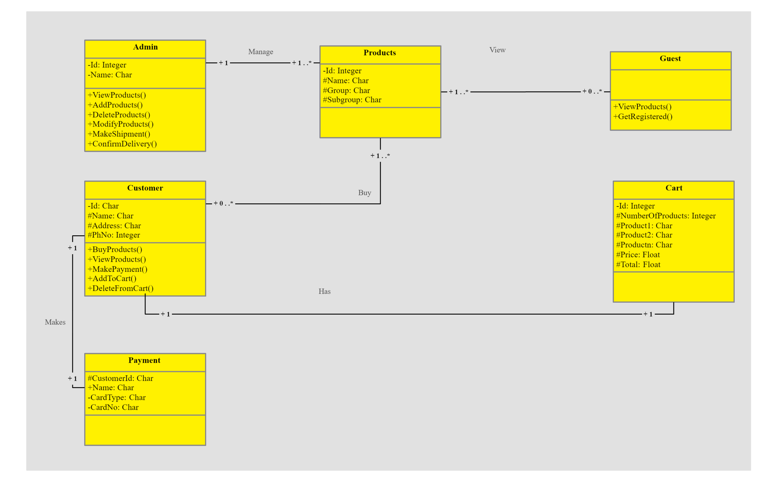
4. Class Diagram for Online Shopping
This online shopping class diagram shows the domain model for online shopping. This diagram will help software engineers and business analysts easily understand the diagram. The diagram links classes like user and account to show how an order is placed and then shipped.

5. Class Diagram for Hospital Management System
If you want to create a hospital management class diagram, this is an excellent template that you can modify per your needs. This domain model shows several class diagrams like a patient, staff, treatment, and the relationships between them.

6. Class Diagram for Banking System
This class diagram for a banking system shows banks, ATMs, customers, etc as different classes. The attributes are listed in the second compartment for each of these and then they are linked together showing the relationship with each. For example, the attributes of a bank can be account number and balance.

7. Class Diagram for Student Registration System
In this class diagram, you can show multiple classes like student, account, course registration manager, course, etc. This class diagram is fairly easy due to its linear design. Registration, course, and account are subclasses of the registration manager and are linked to it using a solid arrow. If your registration system operates a bit differently, then you can add in new classes and easily modify this template.

8. Class Diagram for Airline Reservation System
This Airline Reservation System Class diagram template showcases the classes, their structure, attributes, operations, and relationships. The main classes in the chart shown below are Reservation, passenger, ticket booking, employee, etc. There are multiple dependent and aggregate relationships in this chart as multiple passengers.

Use EdrawMax for Class Diagram Creation
Even though class diagrams are mostly used to model the static view of the system but that's not it. Class diagrams are essential for constructing an executable code for forward or reverse engineering of a system. Other than this, it is an excellent base deployment and component diagrams. However, it is important to use appropriate diagrams for each scenario.
For engineers and amateurs alike, EdrawMax is an excellent tool to create class diagrams to support your documentation and visualize your gadgets and design. With a complete library full of professional class diagram examples , you can easily pick one and modify it as per your needs. Moreover, the user-friendly interface allows anyone from a professional to a beginner to use the software with ease. So, create your class diagrams using EdrawMax easily and quickly.

Diagram Definition: A Case Study with the UML Class Diagram
- Conference paper
- Cite this conference paper

- Maged Elaasar 19 , 20 &
- Yvan Labiche 20
Part of the book series: Lecture Notes in Computer Science ((LNPSE,volume 6981))
Included in the following conference series:
- International Conference on Model Driven Engineering Languages and Systems
2415 Accesses
3 Citations
The abstract syntax of a graphical modeling language is typically defined with a metamodel while its concrete syntax (diagram) is informally defined with text and figures. Recently, the Object Management Group (OMG) released a beta specification, called Diagram Definition (DD), to formally define both the interchange syntax and the graphical syntax of diagrams. In this paper, we validate DD by using it to define a subset of the UML class diagram. Specifically, we define the interchange syntax with a MOF-based metamodel and the graphical syntax with a QVT mapping to a graphics metamodel. We then run an experiment where we interchange and render an example diagram. We highlight various design decisions and discuss challenges of using DD in practice. Finally, we conclude that DD is a sound approach for formally defining diagrams that is expected to facilitate the interchange and the consistent rendering of diagrams between tools.
This is a preview of subscription content, log in via an institution to check access.
Access this chapter
- Available as PDF
- Read on any device
- Instant download
- Own it forever
- Compact, lightweight edition
- Dispatched in 3 to 5 business days
- Free shipping worldwide - see info
Tax calculation will be finalised at checkout
Purchases are for personal use only
Institutional subscriptions
Unable to display preview. Download preview PDF.
Unified Modeling Language (UML), Superstructure v2.4. ptc/2010-11-14
Google Scholar
Business Process Model and Notation (BPMN) v2.0, dtc/2010-06-05
Meta Object Facility (MOF) Core v2.4. OMG ptc/2010-12-08
MOF 2 XMI Mapping v2.4. OMG ptc/2010-12-06
Microsoft Visio (2010), http://office.microsoft.com/en-ca/visio/
Diagram Definition Request for Proposal ad/2007-09-02
Diagram Definition v1.0 FTF Beta 1. ptc/2010-12-18
Booch, G.: Handbook of Software Architecture, http://handbookofsoftwarearchitecture.com
Query/View/Transformation (QVT) v1.0. OMG formal/2008-04-03
Unified Modeling Language (UML), Infrastructure v2.4. OMG ptc/2010-11-03
Object Constraint Language (OCL) v2.2. OMG formal/2010-02-01
Dvorak, R.: Model Transformation with Operational QVT – M2M component, http://www.eclipse.org/m2m/qvto/doc/M2M-QVTO.pdf
Rational Software Architect v8.0 (RSA) Open Beta, https://www14.software.ibm.com/iwm/web/cc/earlyprograms/rational/rsaob/index.shtml
Steinberg, D., Budinsky, F., Paternostro, M., Merks, E.: EMF: Eclipse Modeling Framework, 2nd edn (2009)
Graphical Modeling Framework (GMF), http://www.eclipse.org/gmf/
Model Interchange Wiki, http://www.omgwiki.org/model-interchange/doku.php
Scalable Vector Graphics (SVG) 1.1, http://www.w3.org/TR/SVG/
Diagram Interchange v1.0. formal/06-04-04
MDT Papyrus, http://www.eclipse.org/modeling/mdt/papyrus/
XML Process Definition Language (XPDL), http://www.wfmc.org/xpdl.html
Palies, J.: ATL Transformation Example: UMLDI to SVG (2005), http://www.eclipse.org/m2m/atl/atlTransformations/UMLDI2SVG/UMLDI2SVG0.04.pdf
Atlas Transformation Language (ATL), http://wiki.eclipse.org/M2M/Atlas_Transformation_Language_ATL
DD FTF Wiki, http://www.omgwiki.org/dd/doku.php?id=start
Systems Modeling Language (SysML), v1.2. formal/2010-06-02
Java Emitter Templates (JET), http://www.eclipse.org/modeling/m2t/?project=jet#jet
Balasubramanian, D., Narayanan, A., Buskirk, C., Karsai, G.: The Graph Rewriting and Transformation Language: GReAT. Electronic Comm. of the EASST 1, 1–8 (2006)
Download references
Author information
Authors and affiliations.
IBM Canada Ltd., Rational Software, Ottawa Lab, 770 Palladium Dr., Kanata, ON, K2V 1C8, Canada
Maged Elaasar
Department of Systems and Computer Engineering, Carleton University, 1125 Colonel By Drive, Ottawa, ON, K1S5B6, Canada
Maged Elaasar & Yvan Labiche
You can also search for this author in PubMed Google Scholar
Editor information
Editors and affiliations.
School of Computing and Communications, Lancaster University, InfoLab21, South Drive, LA1 4WA, Lancaster, UK
Jon Whittle
School of Engineering and Information Sciences, Middlesex University, The Burroughs, Hendon, NW4 4BT, London, UK
School of Engineering and Computer Science, Victoria University, P.O. Box 600, 6140, Wellington, New Zealand
Thomas Kühne
Rights and permissions
Reprints and permissions
Copyright information
© 2011 Springer-Verlag Berlin Heidelberg
About this paper
Cite this paper.
Elaasar, M., Labiche, Y. (2011). Diagram Definition: A Case Study with the UML Class Diagram. In: Whittle, J., Clark, T., Kühne, T. (eds) Model Driven Engineering Languages and Systems. MODELS 2011. Lecture Notes in Computer Science, vol 6981. Springer, Berlin, Heidelberg. https://doi.org/10.1007/978-3-642-24485-8_26
Download citation
DOI : https://doi.org/10.1007/978-3-642-24485-8_26
Publisher Name : Springer, Berlin, Heidelberg
Print ISBN : 978-3-642-24484-1
Online ISBN : 978-3-642-24485-8
eBook Packages : Computer Science Computer Science (R0)
Share this paper
Anyone you share the following link with will be able to read this content:
Sorry, a shareable link is not currently available for this article.
Provided by the Springer Nature SharedIt content-sharing initiative
- Publish with us
Policies and ethics
- Find a journal
- Track your research
Solutions for UML Class Diagram exercises
New version in powerpoint, old versions (handwritten).
- All Solutions
(Converted using PowerPoint by Prof. José Ornelas)
Veterinary Clinic
Auto Repair Shop
Furniture Factory
- System Design Tutorial
- What is System Design
- System Design Life Cycle
- High Level Design HLD
- Low Level Design LLD
- Design Patterns
- UML Diagrams
- System Design Interview Guide
- Crack System Design Round
- System Design Bootcamp
- System Design Interview Questions
- Microservices
- Scalability
- Activity Diagrams | Unified Modeling Language (UML)
- Solving Non-Determinism with Blackboard Architecture
- Types of Software Design Patterns
- State Machine Diagrams | Unified Modeling Language (UML)
- 10 Best Python Design Pattern Books for Beginners to Advanced
- Object Diagrams | Unified Modeling Language (UML)
- Conceptual Model of the Unified Modeling Language (UML)
- What is a Swimlane Diagram
- Sequence Diagrams | Unified Modeling Language (UML)
- Difference between Sequence diagram and Collaboration diagram
- Adapter Method | JavaScript Design Patterns
- What are Performance Anti-Patterns in System Design
- Strict consistency or Linearizability in System Design
- Flyweight Design Pattern
- Failure Models in System Design
- Containerization Architecture in System Design
- Design Patterns for Embedded Systems in C
- Goals and Objectives of System Design
- Redis and its role in System Design
Class Diagram | Unified Modeling Language (UML)
Class diagrams are a type of UML (Unified Modeling Language) diagram used in software engineering to visually represent the structure and relationships of classes in a system. UML is a standardized modeling language that helps in designing and documenting software systems. They are an integral part of the software development process, helping in both the design and documentation phases.

Important Topics for the Class Diagram
What are class Diagrams?
What is a class, uml class notation, relationships between classes, purpose of class diagrams, benefits of class diagrams, how to draw class diagrams, use cases of class diagrams.
Class diagrams are a type of UML (Unified Modeling Language) diagram used in software engineering to visually represent the structure and relationships of classes within a system i.e. used to construct and visualize object-oriented systems.
In these diagrams, classes are depicted as boxes, each containing three compartments for the class name, attributes, and methods. Lines connecting classes illustrate associations, showing relationships such as one-to-one or one-to-many.
Class diagrams provide a high-level overview of a system’s design, helping to communicate and document the structure of the software. They are a fundamental tool in object-oriented design and play a crucial role in the software development lifecycle.

In object-oriented programming (OOP), a class is a blueprint or template for creating objects. Objects are instances of classes, and each class defines a set of attributes (data members) and methods (functions or procedures) that the objects created from that class will possess. The attributes represent the characteristics or properties of the object, while the methods define the behaviors or actions that the object can perform.
class notation is a graphical representation used to depict classes and their relationships in object-oriented modeling.

- The name of the class is typically written in the top compartment of the class box and is centered and bold.
- Attributes, also known as properties or fields, represent the data members of the class. They are listed in the second compartment of the class box and often include the visibility (e.g., public, private) and the data type of each attribute.
- Methods, also known as functions or operations, represent the behavior or functionality of the class. They are listed in the third compartment of the class box and include the visibility (e.g., public, private), return type, and parameters of each method.
- + for public (visible to all classes)
- - for private (visible only within the class)
- # for protected (visible to subclasses)
- ~ for package or default visibility (visible to classes in the same package)
Parameter Directionality
In class diagrams, parameter directionality refers to the indication of the flow of information between classes through method parameters. It helps to specify whether a parameter is an input, an output, or both. This information is crucial for understanding how data is passed between objects during method calls.

There are three main parameter directionality notations used in class diagrams:
- An input parameter is a parameter passed from the calling object (client) to the called object (server) during a method invocation.
- It is represented by an arrow pointing towards the receiving class (the class that owns the method).
- An output parameter is a parameter passed from the called object (server) back to the calling object (client) after the method execution.
- It is represented by an arrow pointing away from the receiving class.
- An InOut parameter serves as both input and output. It carries information from the calling object to the called object and vice versa.
- It is represented by an arrow pointing towards and away from the receiving class.
In class diagrams, relationships between classes describe how classes are connected or interact with each other within a system. There are several types of relationships in object-oriented modeling, each serving a specific purpose. Here are some common types of relationships in class diagrams:

1. Association
An association represents a bi-directional relationship between two classes. It indicates that instances of one class are connected to instances of another class. Associations are typically depicted as a solid line connecting the classes, with optional arrows indicating the direction of the relationship.
Let’s understand association using an example:
Let’s consider a simple system for managing a library. In this system, we have two main entities: Book and Library . Each Library contains multiple Books , and each Book belongs to a specific Library . This relationship between Library and Book represents an association.
The “Library” class can be considered the source class because it contains a reference to multiple instances of the “Book” class. The “Book” class would be considered the target class because it belongs to a specific library.

2. Directed Association
A directed association in a UML class diagram represents a relationship between two classes where the association has a direction, indicating that one class is associated with another in a specific way.
- In a directed association, an arrowhead is added to the association line to indicate the direction of the relationship. The arrow points from the class that initiates the association to the class that is being targeted or affected by the association.
- Directed associations are used when the association has a specific flow or directionality, such as indicating which class is responsible for initiating the association or which class has a dependency on another.
Consider a scenario where a “Teacher” class is associated with a “Course” class in a university system. The directed association arrow may point from the “Teacher” class to the “Course” class, indicating that a teacher is associated with or teaches a specific course.
- The source class is the “Teacher” class. The “Teacher” class initiates the association by teaching a specific course.
- The target class is the “Course” class. The “Course” class is affected by the association as it is being taught by a specific teacher.

3. Aggregation
Aggregation is a specialized form of association that represents a “whole-part” relationship. It denotes a stronger relationship where one class (the whole) contains or is composed of another class (the part). Aggregation is represented by a diamond shape on the side of the whole class. In this kind of relationship, the child class can exist independently of its parent class.
Let’s understand aggregation using an example:
The company can be considered as the whole, while the employees are the parts. Employees belong to the company, and the company can have multiple employees. However, if the company ceases to exist, the employees can still exist independently.

4. Composition
Composition is a stronger form of aggregation, indicating a more significant ownership or dependency relationship. In composition, the part class cannot exist independently of the whole class. Composition is represented by a filled diamond shape on the side of the whole class.
Let’s understand Composition using an example:
Imagine a digital contact book application. The contact book is the whole, and each contact entry is a part. Each contact entry is fully owned and managed by the contact book. If the contact book is deleted or destroyed, all associated contact entries are also removed.
This illustrates composition because the existence of the contact entries depends entirely on the presence of the contact book. Without the contact book, the individual contact entries lose their meaning and cannot exist on their own.
.webp "class diagram case study with solution")
5. Generalization(Inheritance)
Inheritance represents an “is-a” relationship between classes, where one class (the subclass or child) inherits the properties and behaviors of another class (the superclass or parent). Inheritance is depicted by a solid line with a closed, hollow arrowhead pointing from the subclass to the superclass.
In the example of bank accounts, we can use generalization to represent different types of accounts such as current accounts, savings accounts, and credit accounts.
The Bank Account class serves as the generalized representation of all types of bank accounts, while the subclasses (Current Account, Savings Account, Credit Account) represent specialized versions that inherit and extend the functionality of the base class.

6. Realization (Interface Implementation)
Realization indicates that a class implements the features of an interface. It is often used in cases where a class realizes the operations defined by an interface. Realization is depicted by a dashed line with an open arrowhead pointing from the implementing class to the interface.
Let’s consider the scenario where a “Person” and a “Corporation” both realizing an “Owner” interface.
- Owner Interface: This interface now includes methods such as “acquire(property)” and “dispose(property)” to represent actions related to acquiring and disposing of property.
- Person Class (Realization): The Person class implements the Owner interface, providing concrete implementations for the “acquire(property)” and “dispose(property)” methods. For instance, a person can acquire ownership of a house or dispose of a car.
- Corporation Class (Realization): Similarly, the Corporation class also implements the Owner interface, offering specific implementations for the “acquire(property)” and “dispose(property)” methods. For example, a corporation can acquire ownership of real estate properties or dispose of company vehicles.
Both the Person and Corporation classes realize the Owner interface, meaning they provide concrete implementations for the “acquire(property)” and “dispose(property)” methods defined in the interface.

7. Dependency Relationship
A dependency exists between two classes when one class relies on another, but the relationship is not as strong as association or inheritance. It represents a more loosely coupled connection between classes. Dependencies are often depicted as a dashed arrow.
Let’s consider a scenario where a Person depends on a Book.
- Person Class: Represents an individual who reads a book. The Person class depends on the Book class to access and read the content.
- Book Class: Represents a book that contains content to be read by a person. The Book class is independent and can exist without the Person class.
The Person class depends on the Book class because it requires access to a book to read its content. However, the Book class does not depend on the Person class; it can exist independently and does not rely on the Person class for its functionality.

8. Usage(Dependency) Relationship
A usage dependency relationship in a UML class diagram indicates that one class (the client) utilizes or depends on another class (the supplier) to perform certain tasks or access certain functionality. The client class relies on the services provided by the supplier class but does not own or create instances of it.
- Usage dependencies represent a form of dependency where one class depends on another class to fulfill a specific need or requirement.
- The client class requires access to specific features or services provided by the supplier class.
- In UML class diagrams, usage dependencies are typically represented by a dashed arrowed line pointing from the client class to the supplier class.
- The arrow indicates the direction of the dependency, showing that the client class depends on the services provided by the supplier class.
Consider a scenario where a “Car” class depends on a “FuelTank” class to manage fuel consumption.
- The “Car” class may need to access methods or attributes of the “FuelTank” class to check the fuel level, refill fuel, or monitor fuel consumption.
- In this case, the “Car” class has a usage dependency on the “FuelTank” class because it utilizes its services to perform certain tasks related to fuel management.

The main purpose of using class diagrams is:
- This is the only UML that can appropriately depict various aspects of the OOPs concept.
- Proper design and analysis of applications can be faster and efficient.
- It is the base for deployment and component diagram.
- It incorporates forward and reverse engineering.
- Class diagrams help in modeling the structure of a system by representing classes and their attributes, methods, and relationships.
- This provides a clear and organized view of the system’s architecture.
- Class diagrams depict relationships between classes, such as associations, aggregations, compositions, inheritance, and dependencies.
- This helps stakeholders, including developers, designers, and business analysts, understand how different components of the system are connected.
- Class diagrams serve as a communication tool among team members and stakeholders. They provide a visual and standardized representation that can be easily understood by both technical and non-technical audiences.
- Class diagrams serve as a blueprint for software implementation. They guide developers in writing code by illustrating the classes, their attributes, methods, and the relationships between them.
- This can help ensure consistency between the design and the actual implementation.
- Some software development tools and frameworks support code generation from class diagrams.
- Developers can generate a significant portion of the code from the visual representation, reducing the chances of manual errors and saving development time.
- Class diagrams encourage the identification of abstractions and the encapsulation of data and behavior within classes.
- This supports the principles of object-oriented design, such as modularity and information hiding.
Drawing class diagrams involves visualizing the structure of a system, including classes, their attributes, methods, and relationships. Here are the steps to draw class diagrams:
- Start by identifying the classes in your system. A class represents a blueprint for objects and should encapsulate related attributes and methods.
- For each class, list its attributes (properties, fields) and methods (functions, operations). Include information such as data types and visibility (public, private, protected).
- Determine the relationships between classes. Common relationships include associations, aggregations, compositions, inheritance, and dependencies. Understand the nature and multiplicity of these relationships.
- Draw a rectangle (class box) for each class identified. Place the class name in the top compartment of the box. Divide the box into compartments for attributes and methods.
- Inside each class box, list the attributes and methods in their respective compartments. Use visibility notations (+ for public, – for private, # for protected, ~ for package/default).
- Draw lines to represent relationships between classes. Use arrows to indicate the direction of associations or dependencies. Different line types or notations may be used for various relationships.
- Label the relationships with multiplicity and role names if needed. Multiplicity indicates the number of instances involved in the relationship, and role names clarify the role of each class in the relationship.
- Review your class diagram to ensure it accurately represents the system’s structure and relationships. Refine the diagram as needed based on feedback and requirements.
- While you can draw class diagrams on paper, using digital tools can provide more flexibility and ease of modification. UML modeling tools, drawing software, or even specialized diagramming tools can be helpful.
- During the system design phase, class diagrams are used to model the static structure of a software system. They help in visualizing and organizing classes, their attributes, methods, and relationships, providing a blueprint for system implementation.
- Class diagrams serve as a visual communication tool between stakeholders, including developers, designers, project managers, and clients. They facilitate discussions about the system’s structure and design, promoting a shared understanding among team members.
- Some software development environments and tools support code generation based on class diagrams. Developers can generate code skeletons, reducing manual coding efforts and ensuring consistency between the design and implementation.
- Testers use class diagrams to understand the relationships between classes and plan test cases accordingly. The visual representation of class structures helps in identifying areas that require thorough testing.
- Class diagrams can be used for reverse engineering, where developers analyze existing code to create visual representations of the software structure. This is especially helpful when documentation is scarce or outdated.
Please Login to comment...
Similar reads.
- Design Pattern
- System Design
- 10 Best Slack Integrations to Enhance Your Team's Productivity
- 10 Best Zendesk Alternatives and Competitors
- 10 Best Trello Power-Ups for Maximizing Project Management
- Google Rolls Out Gemini In Android Studio For Coding Assistance
- 30 OOPs Interview Questions and Answers (2024)
Improve your Coding Skills with Practice
What kind of Experience do you want to share?
UML Diagrams Examples
Examples by technology or application domain, examples by types of diagrams, use case diagrams, business use case diagrams.
System Use Case Diagrams

Information Flow Diagrams

Class Diagrams
Domain Models

Implementation Models

Object Diagrams

Composite Structure Diagrams
Package Diagrams
Component Diagrams
Deployment Diagrams
Network Diagrams

Profile Diagrams
Activity Diagrams
State Machine Diagrams
Sequence Diagrams
Timing Diagrams
Communication Diagrams

Interaction Overview Diagrams
Academia.edu no longer supports Internet Explorer.
To browse Academia.edu and the wider internet faster and more securely, please take a few seconds to upgrade your browser .
Enter the email address you signed up with and we'll email you a reset link.
- We're Hiring!
- Help Center

Class Diagrams Exercises

Related Papers
Klik https://wa.me/6282311607541 obat herbal asam lambung herbal,obat alami asam lambung menurut islam,jual obat herbal asam lambung,obat herbal jika asam lambung naik,jenis obat herbal asam lambung,obat herbal asam lambung kambuh,obat tradisional asam lambung kambuh Qusthul Hindi merupakan tanaman asli India yang memiliki nama ilmiah Saussurea costus. Ekstrak Qusthul Hindi digunakan dalam berbagai pengobatan tradisional, dan dikenal dengan nama minyak atsiri. Qust Al Hindi atau lebih akrab disebut sebagai kayu India mungkin tidak asing. Sebab hal ini lekat dengan salah satu pengobatan ala Rasulullah SAW. Qusthul Hindi atau Indian Costus adalah batang hitam dari tanaman Costus di India. Qusthul Hindi dipercaya untuk pengobatan sejak 2500 tahun lalu di Yunani, Persia, Arab dan India. Informasi dan Pemesanan : Whatsapp 0823-1160-7541 https://wa.me/6282311607541 Apotek Nursyifa Jalan Terusan Buah Batu No. 220 Kota Bandung Pasirluyu Bandung,Pungkur Bandung,Cipedes Bandung,Pasteur Bandung,Sukabungah Bandung,Sukagalih Bandung,Sukawarna Bandung,Gegerkalong Bandung,Isola Bandung,Sarijadi Bandung obat infeksi usus besar,obat infeksi usus alami,obat infeksi usus di apotik,obat infeksi usus buntu,obat infeksi usus 12 jari,obat infeksi usus herbal,obat infeksi usus anak,obat infeksi usus apa ya,obat infeksi usus adalah,obat radang usus alami #obatinfeksiususalami #obatinfeksiususdiapotik #obatinfeksiususbuntu #obatinfeksiusus12jari #obatinfeksiususherbal #obatinfeksiususanak #obatinfeksiususapaya #obatinfeksiususadalah #obatradangususalami #obatradangususanak (WA) 0823-1160-7541 Obat Daya Tahan Tubuh Anak Terbaik Obat Daya Tahan Tubuh Yang Bagus Untuk Anak di Klaten Jawa Tengah
Anniza July
Environment and Planning A
gordon mulligan
jarosław Herbert
Insufficient sleep duration and physical activity (PA) are known risk factors for overweight and obesity in children; however, there are no studies on comprehensive associations of objectively-measured sleep parameters and PA with excess weight and excess adiposity in kindergarteners. Therefore, the aim of this study was to determine the associations between objectively measured sleep parameters and PA with excess weight and excess adiposity, defined as BMI ≥ 85th percentile and body fat percentage (BFP) ≥ 85th percentile, respectively. Sleep parameters and PA were measured in 676 subjects aged 5–6 years using accelerometers for 7 days, worn at the participant’s hip. Bioelectrical impedance analysis was used to estimate BFP. In the total sample, lower sleep duration, sleep efficiency, vigorous PA and the number of steps per day were associated with excess weight. However, excess adiposity was associated with lower sleep duration, total PA, vigorous PA, moderate-to-vigorous physical ...
Ayşenur Benevento
To live like a tree, unique and free Like a forest in harmony, This yearning is ours. Nazim Hikmet This paper deals with two conceptual orientations toward the rights of children: the children’s unconditioned right to recognition, security and protection – necessary prerequisites in order for each and every one of us to be able to live “unique and free”: and the right to be heard and listened to in an unbiased and harmonious dialogue in research settings. More specifically, this paper aims to brings attention to self-determination rights in research settings from children’s and adolescent’s perspective. First, the theoretical background concerning the study of children’s perspectives on their rights will be considered, followed by a focus on children’s participation in research settings.
Joshua Kittle
PROCEEDINGS OF THE INTERNATIONAL CONFERENCE ON MATHEMATICAL SCIENCES AND TECHNOLOGY 2018 (MATHTECH2018): Innovative Technologies for Mathematics & Mathematics for Technological Innovation
Sotiris Moschoyiannis
Literatura Teoria Historia Critica
Ariel Castillo
Journal of Epidemiology & Community Health
Edit Paulik
RELATED PAPERS
Journal of Childhood, Education & Society
Betül Ece Yılmaz
Estudios Geográficos
Rocio Mercadal Perez
Samira Sayedsalehi
Diseases of Aquatic Organisms
edilson matos
Hamed Harharah
Theodore Dejong
roberto aristegui
CHI'E Jurnal Pendidikan Bahasa Jepang (Journal of Japanese Learning and Teaching)
Jurnal Chie
Nephrology Dialysis Transplantation
Renate Kain
maulana akbar
HAL (Le Centre pour la Communication Scientifique Directe)
Antoine Warnery
rtytrewer htytrer
JOURNAL OF ASSOCIATED MEDICAL SCIENCES (Online)
Siramon Sornkla
GAbriel Soto
Antonio Mursia
Food Engineering Reviews
Oliver Handorf
- We're Hiring!
- Help Center
- Find new research papers in:
- Health Sciences
- Earth Sciences
- Cognitive Science
- Mathematics
- Computer Science
- Academia ©2024

Provide details on what you need help with along with a budget and time limit. Questions are posted anonymously and can be made 100% private.

Studypool matches you to the best tutor to help you with your question. Our tutors are highly qualified and vetted.

Your matched tutor provides personalized help according to your question details. Payment is made only after you have completed your 1-on-1 session and are satisfied with your session.
- Homework Q&A
- Become a Tutor
All Subjects
Mathematics
Programming
Health & Medical
Engineering
Computer Science
Foreign Languages
Access over 20 million homework & study documents
Volbank class diagram case study.
Sign up to view the full document!

24/7 Homework Help
Stuck on a homework question? Our verified tutors can answer all questions, from basic math to advanced rocket science !

Similar Documents
working on a homework question?
Studypool is powered by Microtutoring TM
Copyright © 2024. Studypool Inc.
Studypool is not sponsored or endorsed by any college or university.
Ongoing Conversations

Access over 20 million homework documents through the notebank
Get on-demand Q&A homework help from verified tutors
Read 1000s of rich book guides covering popular titles

Sign up with Google
Sign up with Facebook
Already have an account? Login
Login with Google
Login with Facebook
Don't have an account? Sign Up
Finished Papers
As we have previously mentioned, we value our writers' time and hard work and therefore require our clients to put some funds on their account balance. The money will be there until you confirm that you are fully satisfied with our work and are ready to pay your paper writer. If you aren't satisfied, we'll make revisions or give you a full refund.

- Password reminder
- Registration
Customer Reviews
IMAGES
VIDEO
COMMENTS
The solutions should be tested on the following three test cases of increasing size and complexity. These ... 12 Case study: Class diagram restructuring ISO/IEC 9126-1 standard, which is based upon the definition of a Quality Model and its use for software evaluation [1]. This framework defines quality models based on general characteristics ...
UML class diagrams • UML class diagram: a picture of -the classes in an OO system -their fields and methods -connections between the classes • that interact or inherit from each other • Notrepresented in a UML class diagram: -details of how the classes interact with each other -algorithmic details; how a particular behavior is ...
Creating a class diagram to map out process flows is easy. Consider the two examples below as you build your own class diagrams in UML. Class diagram for a hotel management system. A class diagram can show the relationships between each object in a hotel management system, including guest information, staff responsibilities, and room occupancy.
Class diagrams have several use cases. Here are a few examples of how they help developers and businesses: Visualize class relationships. Design class structure. Plan software development. Support code generation. A popular utility of class diagrams is their ability to showcase the class structure of a system.
Case Study Class Diagram. Use Creately's easy online diagram editor to edit this diagram, collaborate with others and export results to multiple image formats. You can easily edit this template using Creately's class diagrams tool. You can export it in multiple formats like JPEG, PNG and SVG and easily add it to Word documents, Powerpoint ...
A class diagram is a UML diagram type that describes a system by visualizing the different types of objects within a system and the kinds of static relationships that exist among them. It also illustrates the operations and attributes of the classes. They are usually used to explore domain concepts, understand software requirements and describe ...
UML - Class diagram case studyWatch more Videos at https://www.tutorialspoint.com/videotutorials/index.htmLecture By: Mr. Arnab Chakraborty, Tutorials Point ...
This case study is an update-in-place refactoring transformation on UML class diagrams. Its aim is to remove clones of attributes from a class diagram, and to identify new classes which abstract ...
Each OOP solution is described using source code, a class diagram, a Nassi-Shneiderman diagram, and a statechart. The three program design criteria described in Chap. 2 are used to evaluate each solution. Download chapter PDF. The objectives of this chapter are to introduce the Address Book Application case study and to apply the program ...
Case study: Class diagram restructuring. K. Lano, S. Rahimi. Published in Transformation Tool Contest 2 September 2013. Computer Science. TLDR. This case study is an update-in-place refactoring transformation used as one of a general collection of transformations which aim to improve the quality of a specification or designlevel class diagram ...
UML Class Diagram Tutorial. The UML Class diagram is a graphical notation used to construct and visualize object oriented systems. A class diagram in the Unified Modeling Language (UML) is a type of static structure diagram that describes the structure of a system by showing the system's: classes, their attributes, operations (or methods),
Diagram Definition: A Case Study with the UML Class Diagram 367 bounds while an edge is laid out as a poly line with a list of waypoint going from a source element to a target element. Also, an element is always rendered on top of its owning element if they overlap. Diagram is a special kind of shape that establishes a
Class diagrams are most important UML diagrams used for software application development. Essential elements of UML class diagram are 1) Class 2) Attributes 3) Relationships. Class Diagram provides an overview of how the application is structured before studying the actual code. It certainly reduces the maintenance time.
For example, the attributes of a bank can be account number and balance. 7. Class Diagram for Student Registration System. In this class diagram, you can show multiple classes like student, account, course registration manager, course, etc. This class diagram is fairly easy due to its linear design.
Recently, the Object Management Group (OMG) released a beta specification, called Diagram Definition (DD), to formally define both the interchange syntax and the graphical syntax of diagrams. In this paper, we validate DD by using it to define a subset of the UML class diagram. Specifically, we define the interchange syntax with a MOF-based ...
How to make a class diagram. Identify all the classes participating in the software solution (from the sequence diagrams). Draw them in a class diagram. Identify the attributes. Identify the methods (from the sequence diagram). Add associations, generalisations, aggregations and dependencies.
Solutions for UML Class Diagram exercises. New version in PowerPoint; Old versions (handwritten) New version in PowerPoint. All Solutions (Converted using PowerPoint by Prof. José Ornelas) Old versions (handwritten) Veterinary Clinic. Auto Repair Shop. Restaurant. Deliveries. Furniture Factory.
Class diagrams are a type of UML (Unified Modeling Language) diagram used in software engineering to visually represent the structure and relationships of classes in a system. UML is a standardized modeling language that helps in designing and documenting software systems. They are an integral part of the software development process, helping in both the design and documentation phases.
Bank ATM UML use case diagrams examples. Point of Sales (POS) terminal. e-Library online public access catalog (OPAC) Online shopping use case diagrams. Credit card processing system. Website administration. Hospital Management. Radiology diagnostic reporting UML use case diagram example. Software protection and licensing UML use case diagram ...
UML Diagrams for the Case Study Library Management. The major components of Unified Modeling Language. UML includes the following 6 diagrams: Class diagram: These diagrams depict the behavioral pattern of the system, i. how each and every class is inter-related to the other one, which relationship exists among each of the classes, etc.
Fuel pump: solution Hose in holster 8 Activity Diagrams Exercises Model processes with activity diagram Booking a Room in a hotel When customer requests a room, the hotel employee looks for room availability, then he insert customer's data and verifies if the provided credit card number has enough credit to pay the room: in this case the ...
Study the Case Study of VolBank given in Schaum’s Outlines 2nd Edition and. Post a Question. Provide details on what you need help with along with a budget and time limit. ... VolBank Class Diagram Case Study ; VolBank Class Diagram Case Study . Content type User Generated. Subject Management. Type Other. Uploaded By nyzn_ovov. Pages 4 ...
Class Diagram Case Study With Solution: Jason. Research Paper $ 14.99. User ID: 766050 / Apr 6, 2022. The first step in making your write my essay request is filling out a 10-minute order form. Submit the instructions, desired sources, and deadline. If you want us to mimic your writing style, feel free to send us your works.