- My presentations

Auth with social network:
Download presentation
We think you have liked this presentation. If you wish to download it, please recommend it to your friends in any social system. Share buttons are a little bit lower. Thank you!
Presentation is loading. Please wait.
Principles, Components & Advantages Hydraulic System Created by : Aamir Shaikh Er No.-130050119501.
Published by Kory Jones Modified over 8 years ago
Similar presentations
Presentation on theme: "Principles, Components & Advantages Hydraulic System Created by : Aamir Shaikh Er No.-130050119501."— Presentation transcript:

Landstown High School Governors STEM & Technology Academy

Fluid Power Systems Mill Creek High School Power and Energy.

Fluid Power Introduction

Hydraulics.

Presented by Jon Pannell

Using Hydraulic Systems. NEXT GENERATION / COMMON CORE STANDARDS ADDRESSED! CCSS.ELA Literacy RST Cite specific textual evidence to support analysis.

AIRCRAFTS HYDRAULIC SYSTEM

Hydraulic Drives and Actuators. Description A hydraulic drive consists of three major parts: The generator (such as a hydraulic pump) driven by an electric.

Intro to Fluid Power Topics What is fluid power? Where is it used?

Muhajir Ab. Rahim School of Mechatronic Engineering

Lesson 5 Fluid Systems.

Chapter 12 Fluid Power. Objectives Upon completing this chapter, you should be able to: –Discuss some fluid power fundamentals –Explain psi, psig, psia,

Chapter 10 Fluid Power Systems.

Hydraulic and Pneumatic Transmission

INTRODUCTION Hydraulics is based on the fact that liquids are incompressible Hydraulic system is a system where liquid under pressure is used to transmit.

Manufacturing Engineering Hydraulic and Pneumatic Systems

Pneumatic and hydraulic actuation systems
About project
© 2024 SlidePlayer.com Inc. All rights reserved.

Introduction to hydraulics
Mar 30, 2019
1.49k likes | 3.26k Views
Introduction to hydraulics. Module 1. Objectives. Identify the three main methods of transmitting power. Identify the common uses of hydraulic systems. Determine that liquids are incompressible. Identify the fundamental parts of a hydraulic system.
Share Presentation
- vehicle power steering
- steering system
- fluid power
- hydraulic oil
- vehicle brake hydraulic systems

Presentation Transcript
Introduction to hydraulics Module 1
Objectives • Identify the three main methods of transmitting power. • Identify the common uses of hydraulic systems. • Determine that liquids are incompressible. • Identify the fundamental parts of a hydraulic system. • Identify the main components of the hydraulic work station TP 501. • Construct a simple hydraulic system using the Hydraulic Work Station TP 501 and related parts. • Explain the main parts of the hydraulic power pack. • Explain the importance of using standard hyrdraulic symbols.
Objectives • Identify the basic hydraulic laws. • Calculate the piston area, force, and pressure. • Explain Pascal’s law and apply it on different examples. • Differentiate between the flow rate and flow velocity. • Demonstrate the continuity equation. • Calculate the area, velocity, and flow rate at different sections of a pipe. • Describe how to read a pressure gauge in the US and SI units. • Set the pressure gauge of the hydraulic power pack to a certain pressure.
Introduction • All machines require some type of power source and a way of transmitting this power to the point of operation. • The three methods of transmitting power are: FLUID
In this course we are going to deal with the third type of power transmission which is the Fluid Power • Fluid power is the method of using pressurized fluid to transmit energy. • Liquid or Gas is referred to as a fluid
There are two branches of Fluid Power
Pneumatics • Pneumatic systems use compressed air to transfer force. • Air is Compressible. • This describes whether it is possible to force an object into a smaller space than it normally occupies. • For example, a sponge is compressible because it can be squeezed into a smaller size
Hydraulics • Hydraulic systems use liquid to transfer force. • Liquid is InCompressible. • Incompressible is the opposite to compressible. • When a “squeezing” force is applied to an object, it does not change to a smaller size. • Liquid, for example hydraulic fluid, possesses this physical property . Hydraulic systems are commonly used where mechanisms require large forces and precise control
Hydraulics • Liquid is ideal for transferring a force from the control mechanism to the mechanism doing the work. • For example transferring force from the brake pedal to the wheel brake in a car. • Because liquid does not compress, it transfers all the force and enables precise movement.
Examples of Hydraulic Systems There are a lot of hydraulic applications in manufacturing, transportation, and construction sectors. Hydraulics systems are used where large, precise forces are required.
Vehicle Brake Hydraulic Systems 2) The pressure forces the brake pads against the brake rotor, which is rotating with the wheel. 3) The friction between the brake pad and the rotor causes the wheel to slow down and then stop. • The function of a vehicle braking system is to stop or slow down a moving vehicle. 1) When the brake pedal is pressed, the hydraulic pressure is transmitted to the piston in the brake caliper of the brakes.
Vehicle Power Steering • The vehicle power steering system uses hydraulic oil, the hydraulic pump supplies the oil through the control valves to the power cylinder. • The major advantage of using this system is to turn the vehicle’s wheels with less effort.
Hydraulic Jack • In a hydraulic jack, a small piston (pumping piston) transmits pressure through the oil to a large piston (power piston) through a check valve, resulting in the weight being lifted.
Aircraft Hydraulic system • All modern aircraft contain hydraulic systems to operate mechanisms, such as: 1. Flaps 2. Landing gear • The hydraulic pump that is coupled to the engine provides hydraulic power. • Power is also distributed to systems through the aircraft by transmission lines. • Hydraulic power is converted to mechanical power by means of an actuating cylinder or hydraulic motor.
- More by User

Introduction to Pneumatics/Hydraulics
Introduction to Pneumatics/Hydraulics. Advance Machining Technology I PDT211. Air Production System. Air Consumption System. What can Pneumatics do?. Operation of system valves for air, water or chemicals Operation of heavy or hot doors
568 views • 16 slides

Hydraulics. hy·drau·lics [ h drólliks ] noun study of fluids: the study of water or other fluids at rest or in motion, especially with respect to engineering applications . Objectives. Behavior of liquids & theory of operation Basic hydraulic system components
903 views • 22 slides

HYDRAULICS. Hydraulics. Teaching Objectives Learn basic concepts Water properties Open channel flow Culvert (or Pipe) flow Variation in hydraulic conditions Temperature and ice effects Flow measurements. Hydraulics Definition.
2.92k views • 69 slides

Power. Hydraulics. Controls. Striving to exceed customer demands by delivering the best. Introduction.
414 views • 10 slides

Introduction to Hydraulics
Introduction to Hydraulics. Introduction to Hydraulics Problem: Calculate the force, F 1 , exerted by the operator to raise a load, F 2 , of 10000N if the piston diameter of the hand pump is 6 mm and the diameter of the load cylinder is 25 mm.
208 views • 2 slides

Hydraulics. hy·drau·lics [ h drólliks ] noun study of fluids: the study of water or other fluids at rest or in motion, especially with respect to engineering applications ( takes a singular verb ) . Objectives. Behavior of liquids & theory of operation Basic hydraulic system components
638 views • 22 slides

Relating Texture to Hydraulics
Relating Texture to Hydraulics. Infiltration . Rapid – water enters at > 7.5 cm (3 in) per hour sand, loamy sand, coarse sandy loam with good structure Moderate – water enters at 0.5 - 7.5 cm (0.2 - 3 in) per hour Very fine and fine sandy loam, sandy loam with weak or moderate structure
155 views • 9 slides

HYDRAULICS. LET’S DO SOME MATH!. Fire Service Hydraulics. During this presentation, we are going to explore the how and why of fire service hydraulics.
1.74k views • 105 slides

Hydraulics. Open Channel Flow. Liquid (water) flow with a ____ ________ (interface between water and air) relevant for natural channels: rivers, streams engineered channels: canals, sewer lines or culverts (partially full), storm drains of interest to hydraulic engineers
926 views • 35 slides

HYDRAULICS. principle.components.structure.application.circuit.h118/1d. Hydraulics. The term “hydraulic” refers to a liquid Hydraulic systems provide a means of remotely controlling a wide range of components by transmitting a force through a confined fluid.
634 views • 21 slides

Introduction to hydraulics. Module 1. Objectives. Identify the common uses of hydraulic systems. Determine that liquids are incompressible. Identify the fundamental parts of a hydraulic system. Observe how hydraulic components can be connected together to construct a hydraulic circuit.
564 views • 18 slides

Hydraulics. How does a hydraulic system work? . Starter: List the main properties of liquids and gases. What are the main similarities/differences between them ? . Glossary words. Pressure – force per unit area acting on surface at right angles to the surface. Unit is pascals (Pa)
398 views • 16 slides

Hydraulics. By: Medha Sesham & Courtney Shadd. Interviewee. Ed Vale Worked at Lexus for 8 years Lexus Service Manager Oversees what happens in the car service area Operates machinery dealing with hydraulics. Functions. Components. Interesting Aspects.
588 views • 6 slides

Hydraulics. Introduction. Hydraulic machinery is machines and tools which use fluid power to do work. Heavy equipment is a common example.
613 views • 17 slides

Hydraulics. Hydraulics. Pumps convert mechanical to hydraulic power. Formulas: Flow: Q ap = (D p N p /231)e Vp where Q ap = actual flow from pump (gph) D p = pump displacement (in. 3 /rev)
663 views • 17 slides

Hydraulics. hy·drau·lics [ h drólliks ] noun study of fluids: the study of water or other fluids at rest or in motion, especially with respect to engineering applications. Objectives. Behavior of liquids & theory of operation Basic hydraulic system components
663 views • 22 slides

Hydraulics . Flows and restrictions. The various components of an hydraulic system can cause flow restrictions and this results in energy losses through the system. Laminar flow although extremely desirable is hard to achieve. Turbulent flow as shown is the norm for
507 views • 32 slides

Hydraulics. Term 2 science due 1/10/13 By Drew Perry. Intro To Hydraulics. Hydraulics are a liquid form of pneumatics Pneumatics are when pressurized gasses are used to produce mechanical rotation. They are used for the generation of control , and transmission of power through fluid.
515 views • 12 slides

Basic Introduction to Hydraulics | just engineering
Just Engineering provides Industrial Hydraulics training and Course with Pumps, motor valves, power units, actuators and hydraulic circuit etc. For More information visit : http://www.justengg.com or call 91 7276030903 / 91 7756911229
361 views • 6 slides

CTC 261 Hydraulics Introduction
CTC 261 Hydraulics Introduction.
325 views • 29 slides

Hydraulics. Hydraulics. hy·drau·lics study of fluids: the study of water or other fluids at rest or in motion, especially with respect to engineering applications. Objectives. Behavior of liquids & theory of operation Basic hydraulic system components
2.99k views • 19 slides

Hydraulics. is defined as the study of fluid behavior, at rest and in motion Properly designed piping with sound hydraulics can: - Greatly reduce maintenance problems over the life of an irrigation system. - Reduce installation cost. Static water pressure. Dynamic water pressure.
518 views • 22 slides
Solutions for
Educator & Staff Training
Improve compliance and deliver critical professional development with online courses and management system
Safety & Compliance
Inclusive Instruction & Interventions
Diversity & Inclusion
School Bus Driver
Cybersecurity Awareness
Facilities Maintenance
Child Sexual Abuse Prevention
Student Safety & Wellness Program NEW
Student Safety & Wellness Program
Keep students safe and healthy with safety, well-being, and social and emotional learning courses and lessons
Substance Misuse Prevention Courses
Mental Health & Well-Being Courses
Healthy Relationships Courses
Personal & Community Safety Courses
Career Readiness & Life Skills NEW
Professional Growth Management
Integrated software to manage and track evaluations and professional development and deliver online training
Professional Development Management
Evaluations Management
Anonymous Reporting & Safety Communications
Empower your school community to ask for help to improve school safety and prevent crises before they occur
Incident & EHS Management
Streamline safety incident reporting and management to improve safety, reduce risk, and increase compliance
Career & Technical Education NEW
Career and Technical Education Solutions
Maximize Student Outcomes with Our All-in-One Work-Based Learning Platform and CTE Courses.
Vector Pathways NEW
CTE Training Courses NEW
Higher Education
Student Training
Increase safety, well-being, and belonging with proven-effective training on critical prevention topics
Sexual Assault Prevention
Alcohol & Drug Misuse Prevention
Diversity, Inclusion, & Belonging
Wellness & Safety
Career & Personal Development NEW
Fraternity & Sorority Life
Faculty & Staff Training
Create a safe, healthy, and welcoming campus environment and improve compliance with online training courses
Harassment, Discrimination, & Sexual Assault Prevention
IT & Campus Security
Health & Safety
Human Resources & Workforce Management
Environmental Health & Facilities Management
Campus Climate Surveys
Simplify VAWA compliance with easy, scalable survey deployment, tracking, and reporting
Empower your faculty, staff, and students to take an active role in protecting themselves and others
Manufacturing
Safety Training NEW
Safety Training
Elevate performance and productivity while reducing risk across your entire organization with online training.
MSHA Training
Industrial Skills Training NEW
Industrial Skills Training
Close skills gap, maximize production, and drive consistency with online training
Core Industrial Skills
Preventative Maintenance
Electrical Maintenance
Continuous Improvement
Power Generation
Paper Manufacturing Training
Enhance worker expertise and problem-solving skills while ensuring optimal production efficiency.
HR & Compliance
Provide role-specific knowledge, develop skills, and improve employee retention with career development training.
Professional Development NEW
DEI Training NEW
Anti Harassment Training NEW
Learning Management System (LMS)
Assign, track, and report role-based skills and compliance training for the entire workforce
Competency Assessments NEW
EHS Management
Track, Analyze, Report Health and Safety Activities and Data for the Industrial Workforce
Incident Management
Inspections & Audits
Real-TIme Safety Metrics and Reports
Behavior-Based Safety
Hazard Reporting
Job Safety Analysis
SDS & Chemical Management
Safety Communication
Enhance the safety for the industrial workforce with two-way risk communications, tools, and resources
Fire Departments
Training Management
A training management system tailored for the fire service--track all training, EMS recerts, skill evaluations, ISO, and more in one place
Training Management System
Skill Evaluations
Firefighter Continuing Education
Online EMS Recertification Training
Fire Academy Automation
Fire Standards and Training
Crew Shift Scheduling
Simplify 24/7 staffing and give firefighters the convenience of accepting callbacks and shifts from a mobile device
Checks & Inventory Management
Streamline truck checks, PPE inspections, controlled substance tracking, and equipment maintenance with a convenient mobile app
Controlled Substance Tracking
Exposure and Critical Incident Monitoring NEW
Exposure and Critical Incident Monitoring
Document exposures and critical incidents and protect your personnels’ mental and physical wellness
Training Management and Recertification
A training management system tailored for EMS services—EMS online courses for recerts, mobile-enabled skill evaluations, and more
EMS Skill Evaluations
EMS Shift Scheduling
Simplify 24/7 staffing and give medics the convenience of managing their schedules from a mobile device
Inventory Management
Streamline vehicle checks, controlled substance tracking, and equipment maintenance with a convenient mobile app
Wellness Monitoring & Exposure Tracking NEW
Wellness Monitoring & Exposure Tracking
Law Enforcement
Training and FTO Management
Increase performance, reduce risk, and ensure compliance with a training management system tailored for your FTO/PTO and in-service training
Training Management System & FTO
Law Enforcement Online Training
Academy Automation
POST and Regulatory Management
Early Intervention & Performance Management
Equip leaders with a tool for performance management and early intervention that helps build positive agency culture
Officer Shift Scheduling
Simplify 24/7 staffing and give officers the convenience of managing their schedules from a mobile device
Asset Mangagement & Inspections
Streamline equipment checks and vehicle maintenance to ensure everything is working correctly and serviced regularly
Energy Skills Training
Empower your team with skills and safety training to ensure compliance and continuous advancement.
Track, analyze, report health and safety activities and data for the industrial workforce
Lone Worker Safety
Enhance lone worker safety with two way risk communications, tools, and resources
Federal Training Management
Lower training costs and increase readiness with a unified system designed for high-risk, complex training and compliance operations.
Military Training Management
Increase mission-readiness and operational efficiency with a unified system that optimizes military training and certification operations.
Local Government Training Management
Technology to train, prepare, and retain your people
Fire Marshall Training & Compliance
Improve fire service certification and renewal operations to ensure compliance and a get a comprehensive single source of truth.
Elevate fire academy training with automation software, enhancing efficiency and compliance.
POST Training & Compliance
Streamline your training and standards operations to ensure compliance and put an end to siloed data.
Law Enforcement Academy Automation
Modernize law enforcement training with automation software that optimizing processes and centralizes academy information in one system.
Simplify incident reporting to OSHA and reduce risk with detailed investigation management.
Architecture, Engineering & Construction
Ensure licensed professionals receive compliance and CE training via online courses and learning management.
Online Continuing Education
Keep AEC staff licensed in all 50 states for 100+ certifications with online training
Architecture
Engineering
Construction
Project Management
Drive organizational success with training that grows skills and aligns with the latest codes and standards
Heath & Safety
Construction and Trades
Track, Analyze, Report Health and Safety Activities and Data for AEC Worksites
Inspections and Audits
Real-Time Safety Metrics and Reports
Enhance AEC workforce safety with two-way risk communications, tools, and resources
Anti-Money Laundering Training
Reduce risk in casino operations with Title 31 and Anti-Money Laundering training compliance
Employee Training
Deliver our leading AML and casino-specific online courses to stay compliant with national and state standards
Streamline training operations, increase employee effectiveness, and reduce liability with our LMS for casinos
Simplify incident reporting to OSHA and reduce risk with detailed investigation management
Employee Scheduling
Equip your employees with a mobile app to manage their schedules and simplify your 24/7 staff scheduling

Industrial Manufacturing
Chemical Processing
Pulp & Paper
Food & Beverage NEW
Utilities NEW
Renewables NEW
Distribution & Logistics
Distribution & Warehousing NEW
Public Safety
EMS Agencies
911 Emergency Communications
State Government - Fire Departments
State Government - Law Enforcement
Local Government
Architecture & Engineering
Facilities Management
Course Center
Success Stories
Speak to an Expert

Resource Center
Expert insights to boost training
Resource type
Course Catalogs
Whitepapers/Guides
Product Brochures
Acquisitions
Vector Cares
Executive Team
Industry Honors

Elevate Training, Elevate Success
Firefighter
See All Industrial Courses
See All AEC Courses
See All Facilities Courses
See All Casino Courses
What Is a Hydraulic System? Definition, Design, and Components
October 23, 2023 14 min read
With a variety of applications, hydraulic systems are used in all kinds of large and small industrial settings, as well as buildings, construction equipment, and vehicles. Paper mills, logging, manufacturing, robotics, and steel processing are leading users of hydraulic equipment.
As an efficient and cost-effective way to create movement or repetition, hydraulic system-based equipment is hard to top. It’s likely your company has hydraulics in use in one or more applications for these reasons.
We’ll provide more information about hydraulic systems in this article, including covering the definition and basic designs and components.
An Overview of Hydraulic Systems
The purpose of a specific hydraulic system may vary, but all hydraulic systems work through the same basic concept. Defined simply, hydraulic systems function and perform tasks through using a fluid that is pressurized. Another way to put this is the pressurized fluid makes things work.
The power of liquid fuel in hydraulics is significant and as a result, hydraulic are commonly used in heavy equipment. In a hydraulic system, pressure, applied to a contained fluid at any point, is transmitted undiminished. That pressurized fluid acts upon every part of the section of a containing vessel and creates force or power. Due to the use of this force, and depending on how it’s applied, operators can lift heavy loads, and precise repetitive tasks can be easily done.
This online hydraulics systems training course illustrates this point.
Marvelously versatile, hydraulic systems are dynamic, yet relatively straightforward in how they work.
Let’s look at some applications and a few basic components found in hydraulic systems. This short sample from our online hydraulic systems and components course sets the scene nicely.
Hydraulic Circuits
Transporting liquid through a set of interconnected discrete components, a hydraulic circuit is a system that can control where fluid flows (such as thermodynamic systems), as well as control fluid pressure (such as hydraulic amplifiers).
The system of a hydraulic circuit works similar to electric circuit theory, using linear and discrete elements. Hydraulic circuits are often applied in chemical processing (flow systems).

Hydraulic Pumps
Mechanical power is converted into hydraulic energy using the flow and pressure of a hydraulic pump. Hydraulic pumps operate by creating a vacuum at a pump inlet, forcing liquid from a reservoir into an inlet line, and to the pump. Mechanical action sends the liquid to the pump outlet, and as it does, forces it into the hydraulic system.

This is an example of Pascal’s Law , which is foundational to the principle of hydraulics. According to Pascal’s Law, “A pressure change occurring anywhere in a confined incompressible fluid is transmitted throughout the fluid such that the same change occurs everywhere.”

Hydraulic Motors
The conversion of hydraulic pressure and flow into torque (or a twisting force) and then rotation is the function of a hydraulic motor, which is a mechanical actuator.
The use of these is quite adaptable. Along with hydraulic cylinders and hydraulic pumps, hydraulic motors can be united in a hydraulic drive system. Combined with hydraulic pumps, the hydraulic motors can create hydraulic transmissions. While some hydraulic motors run on water, the majority in today’s business operations are powered by hydraulic fluid, as the ones in your business likely are.
Hydraulic Cylinders
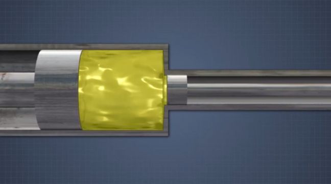
A hydraulic cylinder is a mechanism that converts energy stored in the hydraulic fluid into a force used to move the cylinder in a linear direction. It too has many applications and can be either single acting or double acting. As part of the complete hydraulic system, the cylinders initiate the pressure of the fluid, the flow of which is regulated by a hydraulic motor.

Hydraulic Energy and Safety
Hydraulics present a set of hazards to be aware of, and for that reason safety training is required.
For example, this short sample from our online hydraulic safety training course explains some of the ways the fluids in a hydraulic system can be hazardous.
Remember, the purpose of hydraulic systems is to create motion or force. It’s a power source, generating energy.
Don’t underestimate hydraulic energy in your safety program. It is small but mighty in force. And like any force, it can do great good or great harm.
In the workplace, that translates to a potential hazard source, especially if uncontrolled. Hydraulic energy is subject to OSHA’s Lockout/Tagout rules , along with electrical energy and other similar hazard sources. Be sure to train workers about the hazards of uncontrolled hydraulic energy, especially during maintenance, and the need for lockout/tagout, as illustrated by this still image from one of our online lockout/tagout training courses .

If neglected in procedures or forgotten when servicing equipment, uncontrolled hydraulic energy can have devastating results. Failure to control hydraulic energy frequently causes crushing events, amputations, and lacerations to exposed workers.
Therefore, like other energy sources, hydraulic energy must be controlled, using an appropriate energy isolating device that prevents a physical release of energy. There are also systems that require the release of stored hydraulic energy to relieve pressure. And also, those engaged in lockout/tagout, must also verify the release of stored hydraulic energy/pressure (usually indicated by zero pressure on gauges) prior to working on equipment.
Also, workers need training which must explain the hazard potential and clearly detail methods to prevent injury. According to OSHA:
“All employees who are authorized to lockout machines or equipment and perform the service and maintenance operations need to be trained in recognition of applicable hazardous energy sources in the workplace, the type and magnitude of energy found in the workplace, and the means and methods of isolating and/or controlling the energy.”

Vector EHS Management Software empowers organizations – from global leaders to local businesses – to improve workplace safety and comply with environmental, health, and safety regulations.
Learn more about how our software can save you valuable time and effort in recording, tracking, and analyzing your EHS activities.
Learn more about how we can help:
- Incident Management Software →
- EHS Inspection Software →
- Key Safety Metrics Dashboard →
- Learning Management System (LMS) and Online Training Courses →
- Mobile Risk Communication Platform
Download our EHS Management Software Buyer’s Guide .
You should be very familiar with any equipment in your business that creates hydraulic energy to ensure your workers are adequately protected through well-detailed procedures and training. And of course, your LO/TO program should echo your procedures, and list sources of workplace hydraulic energy devices. (Don’t forget to perform at least annual reviews of the program and procedures to ensure you catch any changes or deficiencies.)
Again, it’s critical anyone involved with hydraulic systems is properly trained. Don’t neglect that aspect.
If you’d like to dig deeper into this topic, we have several courses on hydraulic systems, including Hydraulic System Basics , which outlines the essentials of hydraulic theory, common components, what mechanical advantage is, and how hydraulic fluid is contaminated. In addition, we have two others which provide vital in-depth information, Hydraulic System Valves and Components and Hydraulic System Equipment .
It’s important to understand the principles of these systems, not only for servicing and maintenance, but also to understand the ways the hydraulic systems function to avoid injuries and accidents.
Conclusion: Hydraulics Are Common in the Modern Workplace
Having a working understanding of hydraulics of the type we’ve covered in this article will help you better understand a modern workplace and will make you or your company more efficient, productive, and safe.
Before you go, feel free to download the free guide to manufacturing training below.
Manufacturing Training Guide
Tech, tools, tips, and more!
How to Operate a Forklift: Pre-Operation, Traveling, Load Handling, and Maintenance
OSHA Recordkeeping Assistance in 2024
Related Resources

National Safety Month 2024
June 4, 2024 6 min read
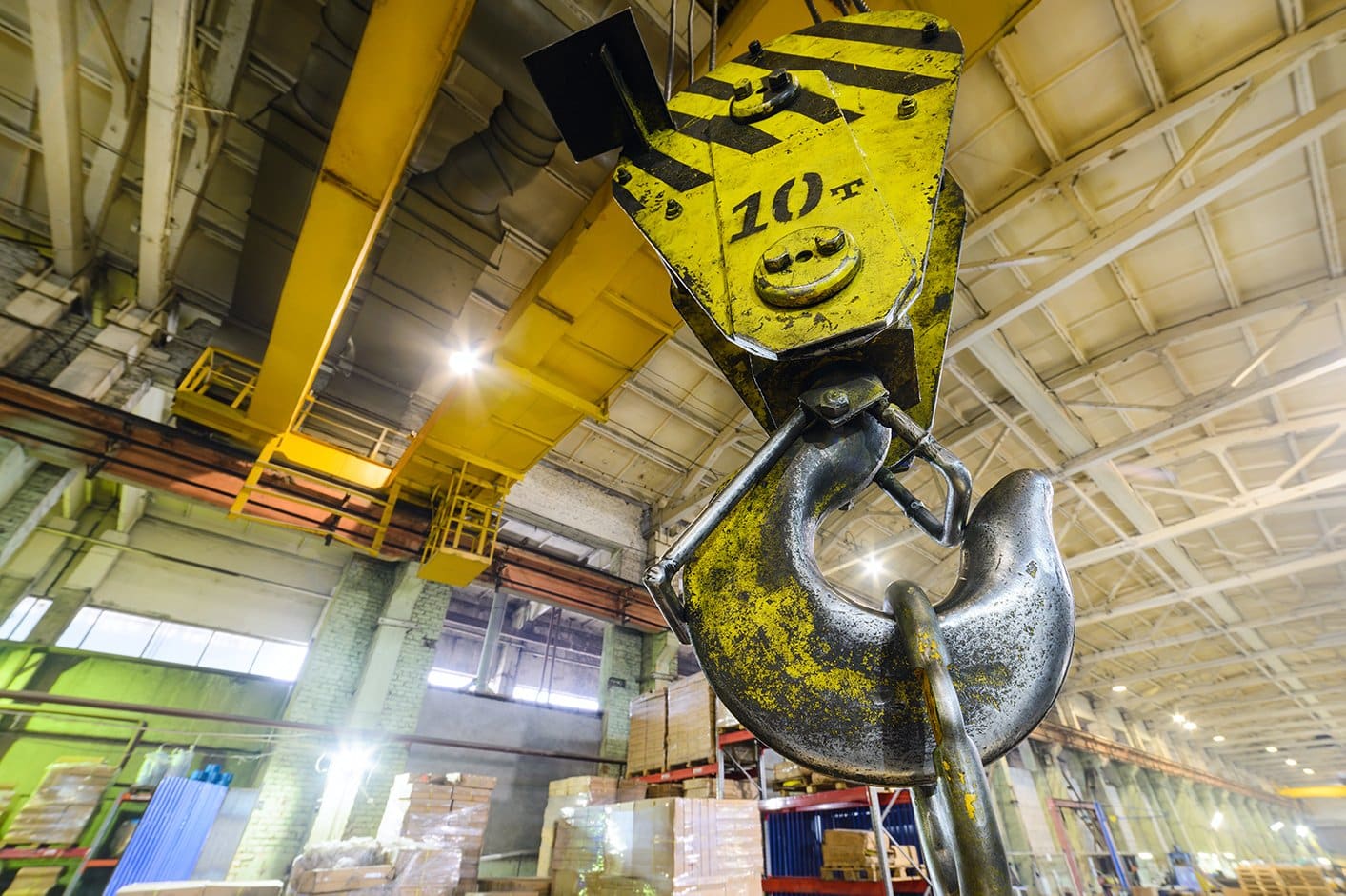
How to Meet OSHA Crane Inspection Requirements
May 30, 2024 9 min read
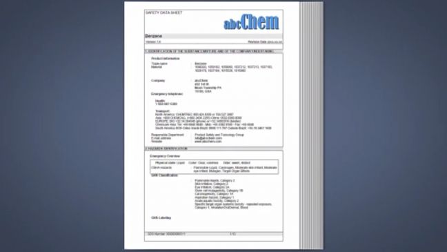
What Is a Safety Data Sheet (SDS)?
May 30, 2024 18 min read

Active Shooter Response Course Preview

OSHA’s “Fatal Four” In Construction: Leading Causes of Fatalities in Construction
May 14, 2024 12 min read

The Three Phases of Risk Assessment: Risk Management Basics
May 7, 2024 4 min read
GHS Label Requirements, Symbols, and Classifications
March 1, 2024 9 min read

OSHA Fire Extinguisher Mounting Height, Placement & Signage Requirements
May 17, 2024 9 min read

Oil and Gas Operator Training Plan

Industrial Workforce at Risk: Report Uncovers Employee Concerns Over Safety, Lack of Training
May 30, 2024
Explore our software solutions designed to help your organization succeed

- Preferences

basics of hydraulics - PowerPoint PPT Presentation

basics of hydraulics
Full basics – powerpoint ppt presentation.
- Explain fundamental hydraulic principles.
- Apply the laws of hydraulics.
- Calculate force, pressure, and area.
- Describe the function of pumps, valves, actuators, and motors.
- Describe the construction of hydraulic conductors and couplers.
- The term hydraulics is used to specifically describe fluid power circuits that use liquidsespecially formulated oilsin confined circuits to transmit force or motion.
- Hydraulic circuits
- Hydraulic brakes
- Power steering systems
- Automatic transmissions
- Fuel systems
- Wet-line kits for dump trucks
- Torque converters
- Pressure applied to a confined liquid is transmitted undiminished in all directions and acts with equal force on all equal areas, at right angles to those areas.
- Hydrostatics is the science of transmitting force by pushing on a confined liquid.
- In a hydrostatic system, transfer of energy takes place because a confined liquid is subject to pressure.
- Hydrodynamics is the science of moving liquids to transmit energy.
- We can define hydrostatics and hydrodynamics as follows
- Hydrostatics low fluid movement with high system pressures
- Hydrodynamics high fluid velocity with lower system pressures
- A column of air measuring 1 square inch extending 50 miles into the sky would weigh 14.7 pounds at sea level.
- If we stood on a high mountain, the column of air would measure less than 50 miles and the result would be a lower weight of air in the column.
- Similarly, if we were below sea level, in a mine for instance, the weight of air would be greater in the column.
- In North America, we sometimes use the term atm (short for atmosphere) to describe a unit of measurement of atmospheric pressure.
- Europeans use the unit bar (short for barometric pressure).
- Force is push or pull effort.
- The weight of one object placed upon another exerts force on it proportional to its weight.
- If the objects were glued to each other and we lifted the upper one, a pull force would be exerted by the lower object proportional to its weight.
- Force does not always result in any work done.
- If you were to push on the rear of a parked transport truck, you could apply a lot of force, but that effort would be unlikely to result in any movement of the truck.
- The formula for force (F) is calculated by multiplying pressure (P) by the area (A) it acts on.
- There are a number of different pressure scales used today but all are based on atmospheric pressure. One unit of atmosphere is the equivalent of atmospheric pressure and it can be expressed in all these ways
- 1 atm 1 bar (European)
- 29.920 Hg (inches of mercury)
- 101.3 kPa (metric)
- However, each of the above values is not precisely equivalent to the others
- 1atm 1.0192 bar
- 1 bar 29.530 Hg 14.503 psia
- 10 Hg 13.60 H2O _at_ 60 F
- Evangelista Torricelli (16081647) discovered the concept of atmospheric pressure.
- He inverted a tube filled with mercury into a bowl of the liquid and then observed that the column of mercury in the tube fell until atmospheric pressure acting on the surface balanced against the vacuum created in the tube.
- At sea level, vacuum in the column in Torricellis tube would support 29.92 inches of mercury.
- A manometer is a single tube arranged in a U-shape used to measure very small pressure values.
- It may be filled to the zero on the calibration scale with either water H2O) or mercury (Hg), depending on the pressure range desired.
- A manometer can measure either push or pull on the fluid column. Examples
- Crankcase pressure
- Exhaust backpressure
- Air inlet restriction
- Absolute pressure uses a scale in which the zero point is a complete absence of pressure.
- Gauge pressure has as its zero point atmospheric pressure.
- A gauge therefore reads zero when exposed to the atmosphere.
- To avoid confusing absolute pressure with gauge pressure
- Absolute pressure is expressed as psia.
- Gauge pressure is usually expressed as psi or psig.
- Hydraulic levers can be used to demonstrate Pascals law
- Pressure equals force divided by the sectional area on which it acts.
- Force equals pressure multiplied by area.
- One of the cylinders has a sectional area of 1sq. and the other 50 sq.
- Applying a force of 2 lbs. on the piston in the smaller cylinder would lift a weight of 100 lbs.
- Applying a force of 2 lbs. on the piston in the smaller cylinder produces a circuit pressure of 2 psi.
- The circuit potential is 2 psi and because this acts on a sectional area of 50 sq., it can raise 100 lbs.
- If a force of 10 lbs. was to be applied to the smaller piston, the resulting circuit pressure would be 10 psi and the circuit would have the potential to raise a weight of 500 lbs.
- Flow is the term we use to describe the movement of a hydraulic fluid through a circuit.
- Flow occurs when there is a difference in pressure between two points.
- In a hydraulic circuit, flow is created by a device such as a pump.
- A pump exerts push effort on a fluid.
- Flow rate is the volume or mass of fluid passing through a conductor over a given unit of time.
- An example would be gallons per minute (gpm).
- Given an equal flow rate, a small cylinder will move faster than a larger cylinder. If the objective is to increase the speed at which a load moves, then
- Decrease the size (sectional area) of the cylinder.
- Increase the flow to the cylinder (gpm).
- The opposite would also be true, so if the objective were to slow the speed at which a load moves, then
- Increase the size (sectional area) of the cylinder.
- Decrease the flow to the cylinder (gpm).
- Therefore, the speed of a cylinder is proportional to the flow to which it is subject and inversely proportional to the piston area.
- In a confined hydraulic circuit, whenever there is flow, a pressure drop results.
- Again, the opposite applies. Whenever there is a difference in pressure, there must be flow.
- Should the pressure difference be too great to establish equilibrium, there would be continuous flow.
- In a flowing hydraulic circuit, pressure is always highest upstream and lowest downstream. This is why we use the term pressure drop.
- A pressure drop always occurs downstream from a restriction in a circuit.
- Pressure drop will occur whenever there is a restriction to flow.
- A restriction in a circuit may be unintended (such as a collapsed line) or intended (such as a restrictive orifice).
- The smaller the line or passage through which the hydraulic fluid is forced, the greater the pressure drop.
- The energy lost due to a pressure drop is converted to heat energy.
- Work occurs when effort or force produces an observable result.
- In a hydraulic circuit, this means moving a load.
- To produce work in a hydraulic circuit, there must be flow.
- Work is measured in units of force multiplied by distance, for example, in pound-feet.
- Work Force x Distance
- Bernoullis Principle states that if flow in a circuit is constant, then the sum of the pressure and kinetic energy must also be constant.
- Pressure x Velocity IN Pressure x Velocity OUT
- When fluid is forced through areas of different diameters, fluid velocity changes accordingly.
- For example, fluid flow through a large pipe will be slow until the large pipe reduces to a smaller pipe then the fluid velocity will increase.
- Flow of a hydraulic medium through a circuit should be as streamlined as possible.
- Streamlined flow is known as laminar flow.
- Laminar flow is required to minimize friction.
- Changes in section, sharp turns, and high flow speeds can cause turbulence and cross-currents in a hydraulic circuit, resulting in friction losses and pressure drops.
- Hydraulic systems can be grouped into two main categories
- Open-center systems
- Closed-center systems
- The primary difference between open-center and closed-center systems has to do with what happens to the hydraulic oil in the circuit after it leaves the pump.
- In an open-center system, the pump runs constantly and oil circulates within the system continuously.
- An open-center valve manages flow through the circuit. When this valve is in its neutral position, fluid returns to the reservoir.
- An example of an open-center hydraulic system on a truck is power-assisted steering.
- In a closed-center system, the pump can be rested during operation whenever flow is not required to operate an actuator.
- The control valve blocks flow from the pump when it is in its closed or neutral position.
- A closed-center system requires the use of either a variable displacement pump or proportioning control valves.
- Closed-center systems have many uses on agricultural and industrial equipment, but on trucks, they would be used on garbage packers and front bucket forks.
- In hydraulics, force is the product of pressure multiplied by area.
- Force Pressure x Area
- For instance, if a fluid pressure of 100 psi acts on a piston sectional area of 50 square inches it means that 100 pounds of pressure acts on each square inch of the total sectional area of the piston. The linear force in this example can be calculated as follows
- Force 100 psi x 50 sq. in. 5000 lbs.
- Accumulators
- Hydraulic motors
- Conductors and connectors
- Hydraulic fluids
- A reservoir in a hydraulic system has the following roles
- Stores hydraulic oil
- Helps keep oil clean and free of air
- Acts as a heat exchanger to help cool the oil
- A reservoir is typically equipped with
- Oil-level gauge or dipstick
- Outlet and return lines
- Intake filter
- The gas and hydraulic oil occupy the same chamber but are separated by a piston, diaphragm, or bladder.
- When circuit pressure rises, incoming oil to the chamber compresses the gas.
- When circuit pressure drops off, the gas in the chamber expands, forcing oil out into the circuit.
- Most gas-loaded accumulators are pre-charged with the compressed gas that enables their operation.
- A fixed-displacement pump will move the same amount of oil per revolution with the result that the volume picked up by the pump at its inlet equals the volume discharged to its outlet per revolution.
- This means that pump speed determines how much hydraulic oil is moved.
- Fixed-displacement pumps are commonly used for applications such as
- Power steering pumps
- Transmission pumps
- Variable-displacement pumps are positive displacement pumps designed to vary the volume of oil they move each cycle even when they are run at the same speed.
- They use an internal control mechanism to vary the output of oil usually with the objective of maintaining a constant pressure value and reducing flow when demand for oil is minimal.
- Gear pumps are widely used in mobile hydraulics because of their simplicity.
- They are also widely used to move fuel through diesel fuel subsystems and as engine lube oil pumps.
- Three types of gear pumps are used
- External gear
- Internal gear
- Two intermeshing gears are close-fitted within a housing.
- One of the gears is a drive shaft and this drives the second gear because they are in mesh.
- As the gears rotate, oil from the inlet is trapped between the teeth and the housing, and is carried around the housing and forced from the outlet.
- A spur gear rotates within an annular internal gear, meshing on one side of it.
- Both gears are divided on the other side by a crescent-shaped separator.
- When an external gear is in mesh with an internal gear, they both turn in the same direction of rotation.
- As the gear teeth come out of mesh, oil from the inlet is trapped between the teeth and the separator and is carried to the outlet and expelled.
- A rotor-gear pump is a variation of the internal-gear pump.
- An internal rotor with external lobes rotates within an outer rotor ring with internal lobes.
- No separator is used.
- The internal rotor is driven within the outer rotor ring. The internal rotor has one less lobe than the outer rotor ring, with the result that only one lobe is fully engaged to the rotor ring at any given moment of operation.
- As the lobes on the internal rotor ride on the lobes on the outer ring, oil becomes entrapped as the assembly rotates, oil is forced out of the discharge port.
- Vane pumps are also used extensively in hydraulic circuits.
- Truck power-assisted steering systems use vane pumps.
- A slotted rotor fitted with sliding vanes rotates within a stationary liner known as a cam ring. There are two types
- As the rotor rotates, centrifugal force moves the vanes outward.
- Fluid is trapped between the crescent-shaped chambers formed between vanes.
- The size of these chambers are continually expanding and contracting as the rotor turns.
- Oil from the inlet is trapped in the space between two vanes.
- As the rotor continues to turn, the chamber contracts until it is aligned with the outlet and the oil is expelled.
- This action repeats itself twice per revolution because there are a pair of inlet ports and a pair of discharge ports.
- This has the same principle as the balanced version, with the exception that the operating cycle only occurs once per revolution because it has only one inlet and one outlet port.
- The disadvantage of the unbalanced vane pump is the radial load caused by high pressure that is acting on the discharge side of the rotor and none on the inlet side because the inlet oil is under little or no pressure.
- There are a wide variety of piston pumps, beginning with the most simple and including some of the more complex pumps used in hydraulic circuits.
- There are three general types of piston pump
- Plunger pumps
- Axial piston
- Radial piston
- Plunger-type pumps are seldom found on hydraulic circuits, but the latter two are used on systems that demand high flow and high-pressure performance.
- A bicycle pump is an example of a plunger pump as are the fuel hand-priming pumps used on many diesel fuel systems.
- A plunger reciprocates within a stationary barrel. Fluid to be pumped is drawn into the pump chamber formed in the barrel on the outward stroke of the plunger.
- This fluid is then discharged on the inboard stroke of the plunger.
- A rotating cylinder with piston bores machined into it rides against an inclined plate.
- The pistons are arranged parallel with the pump drive.
- The base of each piston rides against a tilted plate known as a swashplate or wobble plate which does not rotate.
- They provide a method for controlling the tilt angle of the swashplate.
- Fluid is charged to each pump element as the piston is drawn to the bottom of its travel.
- As the cylinder head rotates, the piston follows the tilt of the swashplate and is driven upward forcing fluid out of the discharge port.
- Radial piston pumps are capable of high pressures, high speeds, high volumes, and variable displacement. However, they cannot reverse flow.
- Radial piston pumps operate in two ways
- Rotating cam
- Rotating piston
- Valves are used to manage flow and pressure in hydraulic circuits.
- There are three basic types of valves used in hydraulic circuits.
- Pressure control
- Directional control
- Volume (flow) control
- Directional control valves direct the flow of oil through a hydraulic circuit. They include
- Check valves
- Rotary valves
- Spool valves
- Pilot valves
- A check valve uses a spring-loaded poppet. It permits flow in one direction and prevents flow in the other.
- A rotary spool turns to open and close oil passages. Rotary valves are commonly used as pilots for other valves in systems with multiple sub-circuits.
- A sliding spool within a valve body to open and close hydraulic circuits. Spool valves are used extensively in hydraulic systems and automatic transmissions.
- Pilot valves may be controlled mechanically, hydraulically, or electrically.
- Hydraulic actuators convert the fluid power from the pump into mechanical work.
- A hydraulic cylinder is a linear actuator.
- A hydraulic motor is a rotary actuator.
- Hydraulic pressure is applied to only one side of the piston.
- Single-acting cylinders may be either
- Outward-actuated When an outward-actuated cylinder has hydraulic pressure applied to it, the piston and rod are forced outward to lift the load. When the oil pressure is relieved, the weight of the load forces the piston and rod back into the cylinder.
- Inward-actuated When an inward-actuated cylinder has hydraulic pressure applied to it, the rod is pulled inward into the cylinder.
- One side of a single-acting cylinder is dry. The dry side must be vented so that when oil pressure on the pressure side is relieved, air is allowed to enter, preventing a vacuum.
- A ram is a single-acting cylinder in which the rod serves as the piston.
- Double-acting cylinders provide force in both directions.
- Pressure is applied to one side of the piston to either extend or retract the cylinder the oil on the opposite side returns to the reservoir.
- Double-acting cylinders may be balanced or unbalanced.
- Balanced double-acting cylinder
- The piston rod extends through the piston head on both sides, giving an equal surface area on which hydraulic pressure can act.
- Unbalanced double-acting cylinder
- A piston rod is located on one side of the piston. There is more surface area on the side without the rod because the rod occupies part of the space on the other side.
- Vane-type cylinders may be found in some much older hydraulic systems.
- A vane-type cylinder provides rotary motion.
- Double-acting vane-type cylinders can be used in applications such as backhoes because they enable a boom and bucket to swing rapidly from trench to pile.
- An alternative to one double-acting vane cylinder for this application would be a pair of opposing cylinders.
- The function of hydraulic motors is the opposite of hydraulic pumps
- It draws in oil and displaces it, converting mechanical force into fluid force.
- Oil under pressure is forced in and spilled out, converting fluid force into mechanical force.
- There are three categories of hydraulic motors
- Gear motors
- Vane motors
- Piston motors
- All hydraulic motors rotate, driven by incoming hydraulic oil under pressure.
- An external-gear motor is driven by pressurized hydraulic oil forced into the pump inlet, which acts on a pair of intermeshing gears, turning them away from the inlet, with the oil passing between the external gear teeth and the pump housing.
- An internal-gear motor is similar to an internal-gear pump. The motor drive shaft is connected to the inner rotor.
- The hydraulic fluid has to be conveyed to various components.
- Mobile hydraulic equipment uses hoses as hydraulic conductors because they
- Allow for movement and flexing
- Absorb vibrations
- Sustain pressure spikes
- Enable easy routing and connection on chassis
- The size of any hydraulic hose is determined by its inside diameter.
- This is sometimes indicated as dash size in 1/16-inch increments.
- Each dash number indicates 1/16 inch,
- a 4 dash hose would be equivalent to 4/16 inch or 1/4 inch.
- Dash size Nominal diameter
- 10 5/8 inch
- 12 3/4 inch
- A large-diameter internal hose has to be stronger to sustain the working pressures of a hydraulic circuit.
- Another consideration for hose selection is that the hose must be compatible with the hydraulic fluid used in the system.
- There are four general types of hoses used in hydraulic circuits
- Fabric braid
- Single-wire braid
- Multiple-wire braid (up to 6 wire braid)
- Multiple-spiral wire (up to 6 wire spirals)
- Hydraulic hose couplers (also known as connectors and fittings) are made of steel, stainless steel, brass, or fiber composites.
- Hose couplers or fittings can either be reusable or permanent.
- Hose fittings are installed at the hose ends and the mating end consists of either a nipple (male fit) or socket (female fit).
- Adapters are separate from the hose and are used to couple hoses to other components such as valves, actuators, or pumps.
- These fittings are crimped or swaged onto the hose.
- When a hose fitted with permanent hose fittings fails, the hose must be replaced either as an assembly or one must be made up using stock hose cut to length fitted with either crimp-type or reusable fittings.
- Reusable fittings are common in truck shops because a hose assembly station, some stock hose, and an assortment of reusable fittings can replace many of the hundreds of different types of hose used on various OEM truck chassis.
- When a hose with reusable fittings wears out, the fittings can be removed and assembled onto new stock hose.
- Reusable fittings are usually screwed onto hose, although some types of low-pressure hose may use press fits.
- Sealing fittings
- Fittings can be sealed to couplers using the following
- Tapered threads
- Nipple and seat (flair)
- When making hydraulic connections, ensure that the coupler fittings are compatible with each other.
- Adapters are separate from the hose assembly. They have the following functions
- To couple a hose fitting to a component
- To connect hydraulic lines in a circuit
- To act as a reducer in a circuit
- To connect a pair of hoses on either side of a bulkhead
- Separation of a fitting and hose at high pressure can be dangerous!
- Never reuse a suspect fitting and observe the manufacturer assembly procedure to the letter.
- When making hydraulic connections, the following guidelines should be observed
- Torque the fitting on the hose, not the hose on the fittings.
- Couple male ends before female ends.
- Ensure the sealing method of each fitting to be coupled is the same.
- Use 45- and 90-degree elbows to improve hose routing.
- Use hydraulic pipe seal compound only on the male threads, and on thread-seal unions.
- Use two wrenches when tightening unions to avoid twisting hose.
- Never over-torque hydraulic fittings.
- When tightening the fittings on a pair of hydraulic couplers, always use two wrenches to avoid twisting hoses or damaging adapters.
- Pipes used in hydraulic circuits are generally made from cold-drawn, seamless mild steel.
- They should never be galvanized because the zinc can flake off and plug up hydraulic circuits.
- Tubing can also be used.
- It has the advantage of being able to sustain some flex hence its use in vehicle brake systems.
- Tubing should be manufactured from cold-drawn steel if used in moderate-to-high-pressure circuits.
- When used in low-pressure circuits, copper or aluminum tubing may be used.
- 45 degrees (SAE standard -- Society of Automotive Engineers)
- 37 degrees (JIC standard -- Joint Industry Committee)
- Inverted flare
- A 45-degree flare is formed inside of the fitting.
- Two-piece flare
- A tapered nut aligns and seals the flared end of the tube.
- Three-piece flare
- A three-piece flare fitting consists of a body, sleeve, and nut and fits over the tube. The sleeve free-floats, permitting clearance between the nut and tube and aligning the fitting. When tightened, the sleeve is locked without imparting twist to the flared tube.
- Self-flaring
- These fittings use a wedge-type sleeve that, as the sleeve is tightened, is forced into the tube end, spreading it into a flare.
- Never attempt to cross-couple SAE and JIC fittings.
- The result will be to damage both.
- Ferrule fittings
- Consist of a body, a compression nut, and a ferrule.
- A wedge-shaped ferrule is compressed into the fitting body by the compression nut, creating a seal between the tube and the body.
- Compression fittings
- These are used with thin-walled tubing and are sealed by crimping the end of the tube to form a seal.
- O-ring fittings
- The principle is similar to ferrule-type fittings except that a compressible rubber compound O-ring replaces the ferrule.
- As the fitting nut is torqued, the O-ring is compressed, forming a seal between the tube and the fitting body.
- Several different types of O-rings are used, including round section, square section, D-section, and steel-backed.
- When hydraulic lines have to be frequently connected and disconnected, a quick release coupler is used.
- A quick coupler is a self-sealing device that shuts off flow when disconnected.
- Quick-release couplers consist of a male and female coupler. There are four types
- Double poppet.
- Sleeve and poppet
- Sliding seal
- Double rotating ball
- Hydraulic fluids used in truck hydraulic systems may be
- Specialty hydraulic oils
- Transmission oil
- Always check when adding to or replacing hydraulic oil.
- Synthetic hydraulic oils are commonly used in todays hydraulic circuits because they have wider temperature operating ranges and offer greater longevity.
- Hydraulic oils must
- Act as hydraulic media to transmit force
- Lubricate the moving components in a hydraulic circuit
- Resist breakdown over long periods of time
- Protect circuit components against rust and corrosion
- Resist foaming
- Maintain a relatively constant viscosity over a wide temperature range
- Resist combining with contaminants such as air, water, and particulates
- Conduct heat
- Truck hydraulic circuits are designed to run at high pressures and support high loads. It is essential that you work safely around chassis hydraulic equipment. Some basic rules
- Never work under any device that is only supported by hydraulics.
- A raised dump box or chassis hoist must be mechanically supported before you work under it.
- Just as when using a floor jack, you must use some means of mechanically supporting any raised equipment or components.
- Hydraulic circuit components can retain high residual pressures.
- The system does not have to be active for this to be a hazard.
- Ensure that pressures are relieved throughout the circuit before opening it up.
- Crack hydraulic line nuts slowly and be sure to wear both safety glasses and gloves.
- Fundamental hydraulic principles include Pascals Law, Bernoullis Principle, and how force, pressure, and sectional area are used in hydraulic circuits to produce outcomes.
- A typical simple hydraulic circuit consists of a reservoir, pump, valves, actuators, conductors, and connectors.
- Hydraulic pumps convert mechanical energy into hydraulic potential.
- Valves manage flow and direction through a hydraulic circuit.
- Actuators such as hydraulic cylinders and motors convert hydraulic potential into mechanical movement.
- Hydraulic oil is used to store and transmit hydraulic energy through a hydraulic system.
- ANSI and ISO graphic symbols are used to represent hydraulic components and connectors in hydraulic schematics.
- Maintenance procedures on truck hydraulic systems begin with ensuring the system is clean both inside and outside the circuit.
- Routine replacement of hydraulic fluid, sometimes accompanied by system flushing, is recommended to minimize system malfunctions and downtime.
- Hydraulic circuit testers are used to analyze hydraulic circuit performance.
- A hydraulic tester consists of flow gauge, pressure gauge, temperature gauge, and gate valve.
PowerShow.com is a leading presentation sharing website. It has millions of presentations already uploaded and available with 1,000s more being uploaded by its users every day. Whatever your area of interest, here you’ll be able to find and view presentations you’ll love and possibly download. And, best of all, it is completely free and easy to use.
You might even have a presentation you’d like to share with others. If so, just upload it to PowerShow.com. We’ll convert it to an HTML5 slideshow that includes all the media types you’ve already added: audio, video, music, pictures, animations and transition effects. Then you can share it with your target audience as well as PowerShow.com’s millions of monthly visitors. And, again, it’s all free.
About the Developers
PowerShow.com is brought to you by CrystalGraphics , the award-winning developer and market-leading publisher of rich-media enhancement products for presentations. Our product offerings include millions of PowerPoint templates, diagrams, animated 3D characters and more.
- Grundfos USA
- All courses
- 75 - The Extended Basic Hyd...
- An introduction to basic hy...
An introduction to basic hydraulic fundamentals
Learn about the most basic hydraulic fundamentals including terms such as flow and head.
When it comes to hydraulics in water pumping systems, we need to consider three major parameters: Flow, head and power – or Q, H and P.
In this short module, we’re going to introduce you to these basic parameters and what they mean for each other. Let’s get started.
Flow (Q) is typically measured in ft3/h. Simply put, the flow describes the amount of water that a pump moves through pipes within a given time period.
This is exactly why it is measured in ft3/h. The head (H) of a pump is the pressure that it is able to provide. It describes the height to which the pump can elevate water. So, if a pump’s head is, say, 60 feet, it means that it can lift water 60 feet in the air.
Finally, there’s the power (P). As the name suggests, power denotes the force and speed at which the water is moved. The power is measured in kilowatt.
As the power is dependent on the aforementioned flow (Q) and head (H), you can measure it by using the following formula: P = Q x H x c. In this calculation, c is a constant which depends on your pump’s efficiency, the level of gravity, and the fluid you are pumping.
Keep in mind that if you double the pump’s flow or head, you automatically double the pump’s power. And if you double both the flow and the head, you quadruple the energy usage.
That just about covers our introduction to the fundamentals of basic hydraulics. Thanks for tuning in.
Course overview
COMMENTS
Hydraulic system. Oct 6, 2015 • Download as PPTX, PDF •. 52 likes • 28,878 views. AI-enhanced description. Gopal Carpenter. The document summarizes key concepts in hydraulics including: 1. Hydraulics uses liquids to transmit force via Pascal's law, where pressure is transmitted undiminished throughout a confined liquid. 2.
18 Conductors: The conductors are the pipes or hoses needed to transmit the oil between the hydraulic components. Download ppt "Introduction to hydraulics". Objectives Identify the common uses of hydraulic systems. Determine that liquids are incompressible. Identify the fundamental parts of a hydraulic system.
Hydraulic Mid Inlets 29. Power Beyond 30. Open Center Schematic 31. Closed Center LS Schematic 32. Horse Power Consumption 33. Hydraulic Cylinders 34. Single Acting Double Acting Cylinders 35. Bleeding Air 36. Hydraulic Motor Types 37. How Motors Work 38. Filtration 39. How Filters are Selected 40. PTO Types 41. Manual PTO's 42
Hydraulic • Two Greek word, hudro (Water) + aulos (Pipe) → hudraulikos • hudraulikos (Greek) → hydraulic (Latin) early 17th century • Hydraulics is the science of forces and movements transmitted by means of liquids. • Pressurized liquid act as a medium of power transmission. • Hydraulic fluids are incompressible.
1.6 -Basic Construction of Hydraulic Systems, 37 1.7- Advantages and Limitations of Hydraulic Systems, 40 1.7.1- Use of Hydraulic Fluids, 40 1.7.2- Power Transmission, 41 1.7.3- Controllability and System Design, 42 1.8- Industry Standards for Hydraulic Systems, 43
Pump Power. Hydraulic power is the product of pressure and flow rate. Across a circuit with the same flow in as out, the power change: Ph = Q∆p / 60 Where Ph = hydraulic power, kW Q = flow through device, L/min ∆p = pressure rise or drop across device or circuit, MPa.
Unit 1 - Introduction to Hydraulic System - Free download as Powerpoint Presentation (.ppt), PDF File (.pdf), Text File (.txt) or view presentation slides online. This document provides an introduction to hydraulic systems. It defines hydraulics as technology that generates, controls, and transmits power using pressurized liquid. The main advantages of hydraulic systems are easy control, force ...
3 3 Basic Principle Basic principle of a hydraulic system are: -Prime mover to power the system -Pump to move fluid -Reservoir to store fluid -Relief valve or pump compensator to control maximum system pressure -Filter to clean the fluid -Plumbing to transport fluid to components. 4 4 Basic Principle. 5 Basic Components The major ...
this chapter, we shall discuss a structure of hydraulic systems and pneumatic systems. We will also discuss the advantages and disadvantages and compare hydraulic, pneumatic, electrical and mechanical systems. 1.2 Fluid Power and Its Scope Fluid power is the technology that deals with the generation, control and transmission of ...
A hydraulic system uses pressurized liquid to generate, control, and transmit power. It has several advantages over mechanical and electrical systems including easy control, force multiplication, constant force regardless of speed changes, and compact construction. The key components are a pump, reservoir, valves, actuator, and piping. Pascal's law states that pressure in a confined fluid is ...
Presentation Transcript. Introduction to hydraulics Module 1. Objectives • Identify the three main methods of transmitting power. • Identify the common uses of hydraulic systems. • Determine that liquids are incompressible. • Identify the fundamental parts of a hydraulic system. • Identify the main components of the hydraulic work ...
Hydraulic pumps operate by creating a vacuum at a pump inlet, forcing liquid from a reservoir into an inlet line, and to the pump. Mechanical action sends the liquid to the pump outlet, and as it does, forces it into the hydraulic system. This is an example of Pascal's Law, which is foundational to the principle of hydraulics.
25. Calculating Force. In hydraulics, force is the product of pressure. multiplied by area. Force Pressure x Area. For instance, if a fluid pressure of 100 psi acts. on a piston sectional area of 50 square inches it. means that 100 pounds of pressure acts on each. square inch of the total sectional area of the.
An introduction to basic hydraulic fundamentals. Learn about the most basic hydraulic fundamentals including terms such as flow and head. When it comes to hydraulics in water pumping systems, we need to consider three major parameters: Flow, head and power - or Q, H and P.
Hydraulic Presentation.ppt - Free download as Powerpoint Presentation (.ppt), PDF File (.pdf), Text File (.txt) or view presentation slides online. This document discusses hydraulic systems and their components. It covers two basic types of hydraulics - hydrodynamics which uses fluids at high speed and hydrostatics which uses fluids at low speed and high pressure.
Explaining Basic Hydraulic System Circuit Components along with the Working Animation
The hydraulic systems consists a number of parts for its proper functioning. These. include storage tank, filter, hydraulic pump, pressure regulator, control valve, hydraulic. cylinder, piston and ...
18. Working of Hydraulic system A simple hydraulic system consists of a pump which pumps oil to a hydraulic ran. This pump may be driven from tractors transmission system or it may be mounted on its engine. This system consists of a cylinder with a close filling piston like an engine cylinder. As the oil is pumped in to the closed end of the ...
For more and related videos :https://www.youtube.com/channel/UCpdWMqUKAErpyRt6IBY2GKA?sub_confirmation=1